
RCP CL Comm Intermediate Stream Mixed Type Example
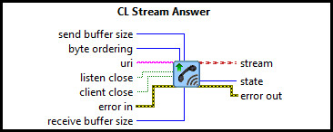
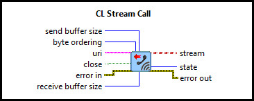
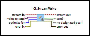
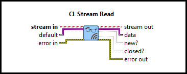
This example consists of two communication VIs: a server and a client. It demonstrates how to use the CL Stream Call, CL Stream Answer, CL Stream Write, CL Stream Read VIs from the Quanser Rapid Control Prototyping Toolkit to establish a connection between two VIs. For a detailed description of these VIs and how they operate, please refer to the RCP CL Stream Answer, CL Stream Call, CL Stream Write, and CL Stream Read help pages.
System Requirements
Please refer to the Rapid Control Prototyping (RCP) Toolkit System Requirements to run this example. This example does not require any other hardware.
Configuring the Example
Open the RCP CL Comm Intermediate Stream Client Mixed Types Example.vi and the
                RCP CL Comm
                Intermediate Stream Server Mixed Types Example.vi
under My Computer. To set up the example, select
Show Block Diagram from the Window menu or press Ctrl+E while the Front Panel is the
active window for both the RCP CL Comm Intermediate Stream Client Mixed Types Example.vi and
                RCP
                CL Comm Intermediate Stream Server Mixed Types Example.vi
. Ensure that the URI for the server and
client are the same in the pink text box, since both VIs run on the same machine. An example of a valid URI is
tcpip://localhost:18000. The RCP URIs are described on the
Universal Resource Identifiers page. Close the Block Diagram
window after all changes to the VI have been made.
Running the Example
Click on the button for each VI or select from the menu to start each VI. A straight line with an amplitude of 0 will
appear in the Data Sent # and Data Received # graphs. Notice that the graph trace
is now moving in real time. In other words, the trace passes the 5-second mark after 5 seconds have passed.
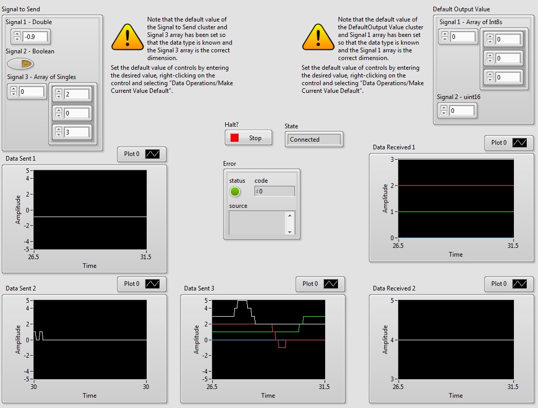
On the server and/or client VI, the Signal to Send can be changed by modifying the values of
Signals #1, 2, or 3 in the top left
corner. The output of the server and client VIs can be visually seen in the Data Sent # graphs.
If Signal 3 - Array of Singles changes to
[1 2 3] graph Data Sent 3 will display this data.
If the server is sending data, the client will be able to show the data sent (and received)
on the Data Received graph.
For example if the server changes the value of Signal 1 to equal 4,
Data Received 1 on the client side will
display the change.
Before the server and/or client VIs are connected, but running,
the Data Received graphs take on the values defined
in the Default Output Value section in the top right corner.
When connection is established the data received values will change
to the values that the server and client VIs send.
For example if the server VI is running and its default output value for Signal 1 is 10 and
the client isn't connected, then the value in the server's Data Received graph is 10.
If the client VI then connects to the server and sends the
value 4, the server's Data Received graph will change to 4.
When the server and/or client VIs become disconnected, but running,
the data plotted in the Data Received graphs
are (re-)set to the ones defined in the Default Output Value section in the top right corner.
Click on the Front Panel button to stop the VI.
Copyright © Quanser Inc. This page was generated 2024-11-15. Submit feedback to Quanser about this page.
Link to this page.