
Achieving Optimal Performance
With its tight integration with Simulink and flexibility in tuning parameters and monitoring signals, QUARC makes it easy to develop real-time applications quickly. However, once those applications are designed, it is often desirable to generate production code for the final product. There are also circumstances in which very high performance is required, and the overhead of communicating with Simulink must be eliminated to achieve the highest possible performance. This section describes how to generate code to achieve the optimal performance with QUARC. It is divided into subsections so that varying levels of performance may be obtained by choosing the performance-enhancing options desired.
Optimizing the Generated Code
QUARC fully supports the optimization options available with Simulink Coder. Open the Configuration Parameters dialog or go to the active configuration in Model Explorer using one of the procedures outlined in the Configuring a Model section of the QUARC documentation. Click on the Optimization item in the configuration parameters, as illustrated below.
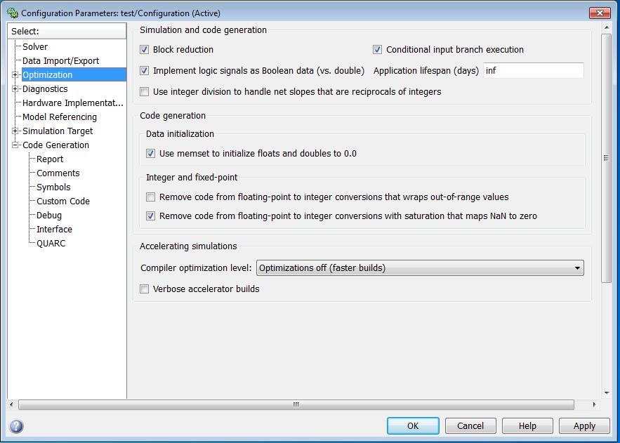
Some of the optimizations will already be selected, such as block reduction and signal storage reuse. A full explanation of all the options on the page is available just by clicking the button on the Configuration Parameters dialog. There is one key optimization, the Inline parameters option, which is not selected by default, however, because it affects the tunability of parameters in the model. By default, almost all the parameters in the model may be tuned while the model is running. This flexibility, however, comes with a cost. To be tunable, each parameter must be assigned to a variable in the code, even if that parameter will never change during the model execution. Thus, the compiler cannot optimize much of the code, because it cannot assume that these parameters can be pre-evaluated or even optimized right out of the code, because their value may change.
To generate more optimized code, check the Inline parameters option. Doing so causes all parameters in the model to be assumed to be constant. Many parameters will appear as their constant value in the generated code, allowing the compiler to optimize much more readily because it can now pre-evaluate expressions, move some expressions out of loops by precomputing them and even completely eliminate sections of code that will never execute.
If some parameters still need to be tunable, replace those parameter values with
a MATLAB workspace variable. Make sure each MATLAB workspace variable used as a
parameter is assigned a value. Then return to the Configuration Parameters dialog's
Optimization pane, and click on the
button after selecting the Inline parameters
option. The Model Parameter Configuration dialog will open, which allows a subset
of the parameters assigned to MATLAB workspace variables to be maintained as tunable
parameters, while the rest of the parameters are inlined. The Model Parameter Configuration
dialog is illustrated below for a simple diagram containing a Sine Wave
feeding a Scope block. The
amplitude of the sine wave has been assigned to a MATLAB workspace variable called
amp, with a value of 5.0.
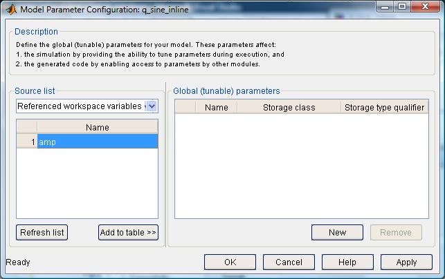
The combobox has been set to display
only those MATLAB workspace variables that are actually referenced in the model.
Even though the Sine Wave has several parameters,
including amplitude, frequency, phase and bias, only the amplitude is assigned to
a MATLAB workspace variable: amp. Hence, only the amp
variable appears in the list. In this image, the amp variable has been
selected by clicking on its name in the list.
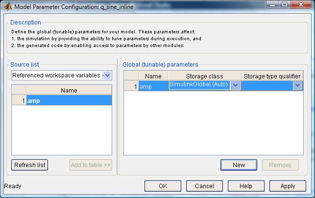
By selecting a variable from the list, the
button becomes enabled. Click on this button to add the amp variable
to the list of tunable parameters. The amplitude of the sine wave will now be tunable
in the generated code, even though the other parameters, such as the sine wave frequency
and phase, will not be tunable. The appearance of the Model Parameter Configuration
dialog after choosing to add the amp variable to the table of global
tunable parameters is depicted below.
Now click on to record the changes and close the dialog. Once the real-time code has been built, a glance at the code will reveal that the sine wave frequency is a constant but the amplitude is still tunable. For example, the sample code may look like the following:
/* Sin: '<Root>/Sine Wave' */
q_sine_inline_B.SineWave = sin(6.2831853071795862E+000 * q_sine_inline_M->Timing.t[0]) * q_sine_inline_P.amp;
In this case, the sine wave frequency was 2π rad/s, which has been replaced with
its computed value because the sine wave frequency is inlined. Unlike the other
parameters, the sine wave amplitude remains as a variable called q_sine_inline_P.amp
because it was explicitly configured as a tunable parameter. To tune the amplitude
in external mode while connected to the real-time code, modify the amp
variable in the MATLAB workspace. Then update the Simulink diagram, either by clicking
on the model window and pressing Ctrl+D, or by selecting
from its menu, or by using QUARC's qc_update_model function. As soon as the
model is updated, the parameter change will take place.
Other optimization options which can improve the efficiency of the generated code are the "Ignore integer downcasts in folded expressions", "Inline invariant signals" and "Remove code from float-point to integer conversions that wraps out-of-range values" options. All of these parameters are useful for optimizing the generated code and should be selected, in general, for the fastest code. For more information on these and other options in the Optimization pane, click on the Help button in the Configuration Parameters dialog when this pane is selected. After modifying the configuration parameters, close the dialog by clicking and then rebuild the model.
Disabling External Mode
QUARC provides the ability to connect to the real-time code from the Simulink model and monitor signals in the real-time code using Scopes and other sink blocks, and to tune the parameters of the model just by changing block parameters in the diagram. This ability to stream data from the real-time code and to tune parameters does exact a price. For remote targets, it will use up network bandwidth as data is streamed from the real-time code back to Simulink. It also may affect the jitter in the sample time if the drivers for the network card use Direct Memory Access (DMA) to interface with the card. DMA steals bus cycles from the CPU and can interfere with real-time performance - even in an operating system designed for hard real-time performance. QUARC does perform its communications with the Simulink diagram from separate threads that run at a lower priority than the code for the model itself, so the communications do not interfere directly with the real-time performance. But factors such as DMA and the extra CPU cache flushing that can result from having more thread context switches can introduce more jitter into the sample time. Thus, truly optimal performance in QUARC is achieved only when external mode is disabled.
Besides the potential performance gains, disabling external mode is often desirable for production code because connecting to the real-time code from Simulink is no longer required. The model is already tuned and working properly. Now, the most important goal is typically to reduce the size of the model code. By eliminating the code used to communicate with Simulink, this size reduction can not only be achieved, but the performance of the real-time code may even be improved.
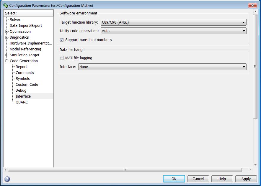
To disable external mode, open the Configuration Parameters dialog or go to the active configuration in Model Explorer using one of the procedures outlined in the Configuration a Model section of the QUARC documentation. Go to the Interface tab under the Code Generation section. The Interface tab is shown below.
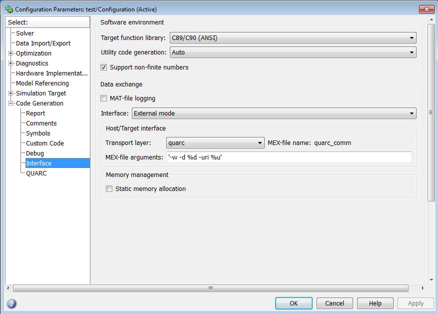
Notice that under the Data Exchange panel, the Interface field is set to External mode. It is this field that enables external mode so that the Simulink diagram may be used to communicate with the real-time code on the QUARC target. To disable such external interfacing, choose None from this dropdown list. The rest of the fields for external mode will disappear because they are no longer necessary. This situation is depicted below.
Click to save the changes and close the dialog.
Then rebuild the code. It will no longer be possible to connect to or run the generated
code from Simulink. Nor will the -w and -uri options be
supported as model arguments because these two options are specific to external
mode. To run the generated code, use Windows Explorer as described in the
Using Windows Explorer to Manage Models section of the QUARC documentation.
The Windows Explorer interface may also be used to open a QUARC Console to monitor
the standard I/O of the real-time process, as well as to stop the model or configure
the model to load at boot on the target.
One concern when disabling external mode is whether it will still be possible to
collect data from the real-time code, since Simulink may no longer be used. The
simplest and least obtrusive way to collect data from the real-time code, in this
case, is to use MAT-file logging. QUARC's MAT-file logging feature stores data in
a circlar memory buffer until the model is stopped, and only then does it write
the data to disk. The data is stored in a MAT file, with the same name as the model,
on the target. For example, a model called q_sine will create a MAT
file called q_sine.mat when MAT-file logging is enabled. Signals routed
to root-level Outport
MATLAB Command Line
Click to copy the following command line to the clipboard. Then paste it in the MATLAB Command Window:
doc Outport blocks,
model states and other variables may be stored in the MAT-file. MAT-file logging
does not interfere with real-time performance because the disk is not accessed while
the real-time code is running, and the data is not streamed to the host, so no DMA
is involved. For more information about MAT-file logging, including how to select
the signals to be logged and to enable MAT-file logging, refer to the
MAT-file Logging section in the QUARC documentation.
Increasing the Priority of the Real-Time Code
When a new model is created, QUARC assigns a minimum base priority to the model that is generally suitable for real-time performance. For example, for the QUARC Windows target, it assigns the lowest priority among the real-time priority class in Windows. This priority gives real-time code higher priority than almost all other Windows processes, including device drivers such as the mouse and keyboard. Likewise, in Linux, a minimum base priority of 20 is assigned to new models, because most processes in Linux run at a priority level of 10. Thus, real-time code once again is given a higher priority than most other processes in the system. Thus, it is rarely necessary to change the priority of the real-time code. However, when multiple models are being run on the target, or some operating system components or other applications are found to be running at a higher priority than the default, then QUARC allows the base priority of a model to be changed.
To change the base priority of a model, open the Configuration Parameters dialog or go to the active configuration in Model Explorer using one of the procedures outlined in the Configuration a Model section of the QUARC documentation. Go to the QUARC tab under the section. The QUARC tab is shown below.
Make sure the Debug version and Support dynamic reconfiguration options are not checked, in order to achieve optimal performance. If dynamic reconfiguration capabilities are required, then leave that option checked. The key parameter for this section is the Minimum thread priority field. This field defines the priority that will be assigned to the lowest priority task in the model. Hence, in a multi-rate model, this priority will be assigned to the slowest task in the model. The only exception is when external mode is enabled, in which case the priority of the tasks will be increased, if necessary, to ensure that the slowest task is still higher priority than the two threads used for external mode communications. Note that the priority of asynchronous threads is independent of the minimum thread priority. For more information about setting the priority of threads in the real-time code, refer to the Code Generation Pane - QUARC section of the QUARC documentation.
 Note that arbitrarily increasing the minimum thread priority will not increase the
performance of the real-time code unless there is another process in the system
with higher priority. Also, the priority only relates to other threads. It is not
possible to give priority over DMA, sections of code with interrupts disabled, or
other situations where the operating system gives precedence over all threads in
the system. In general, the priority should be set at a level that gives precedence
where required, but leaves room for other processes to be given a higher priority
in the future, if necessary.
Note that arbitrarily increasing the minimum thread priority will not increase the
performance of the real-time code unless there is another process in the system
with higher priority. Also, the priority only relates to other threads. It is not
possible to give priority over DMA, sections of code with interrupts disabled, or
other situations where the operating system gives precedence over all threads in
the system. In general, the priority should be set at a level that gives precedence
where required, but leaves room for other processes to be given a higher priority
in the future, if necessary.
Copyright ©2026 Quanser Inc. This page was generated 2026-05-13. Submit feedback to Quanser about this page.
Link to this page.