
Altia Plot
Sends a signal for plotting on a Quanser Altia Plot component.
Library
QUARC Targets/User Interface/Altia MATLAB Command Line Click to copy the following command line to the clipboard. Then paste it in the MATLAB Command Window: qc_open_library('quarc_library/User Interface/Altia')
Description
The Altia Plot block sends its input signal to a Quanser Altia Plot component for plotting. The signal may be a vector, in which case the Quanser Altia Plot component must be configured to plot the same number of lines as the signal dimension.This block never waits for the Altia GUI to receive the new signal value. It always returns immediately. The sent output indicates whether the data has been sent or not.
The Quanser Altia Plot component is installed with QUARC and is located under the
QUARC tree under altia\models in the plots.dsn library.
Open the library from Altia using the button
and browse to the location of the plots.dsn library. For example,
if QUARC is installed in the C:\Program Files\Quanser\QUARC directory,
then the Quanser Altia Plot components are found in the file
C:\Program Files\Quanser\QUARC\altia\models\plots.dsn.
Click the following link to browse to the
models
MATLAB Command Line
Click to copy the following command line to the clipboard. Then paste it in the MATLAB Command Window:
dos(['explorer ', fullfile(getenv('QUARC_DIR'), 'altia', 'models')]); folder.
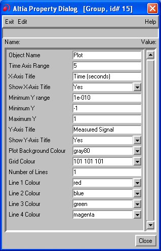
Drag a Plot component into your Altia GUI from the plots.dsn library.
Double-click on the Plot component to open its properties and set the number of
lines to match input to the Altia Plot block in
the Simulink diagram. Choose the time axis and Y-axis ranges as well. Note that
changing the Y-Axis Minimum property does not
change the Y-axis range. The Y-axis range does not change until the Y-Axis Maximum
is also modified. The Plot component may modify the range
slightly to ensure that the grid lines are aligned on "nice" numbers.
To use the Altia Plot block, an Altia Initialize
block must be present in the diagram and be associated
with an Altia design file. The Quanser Altia Plot component's nextpoint
connection is selected in the Events listbox. Do not
connect to any other external connection. The list of events is populated from all
the external output connections specified in the Altia design. External output connections
are created in Altia by selecting
from the menu. The External Connections
dialog shown below will appear:
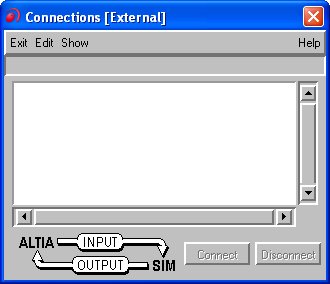
Select from the menu of this dialog. Enter a name for the connection and an animation name. The animation name is the name that will appear in the Events listbox. It must be unique throughout the Altia design. Choose the radio button to indicate that this connection will be an output i.e. a signal sent to Altia from the real-time code or "SIM" as it is indicated in the dialog.
Once the external connections have been defined, you need to connect them to an Altia GUI component for them to manipulate the Altia GUI. Keep the External Connections dialog open. Select the item from the menu. The dialog shown below will appear.
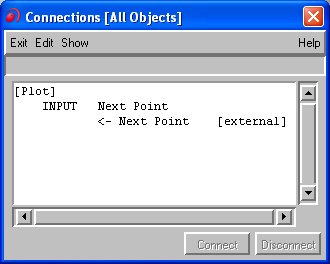
Select one of the component's input signals in the Connections dialog. Also select the corresponding output connection in the External Connections dialog. The button should become enabled. Click on the button to establish the link between the external connection visible to Simulink and the component.
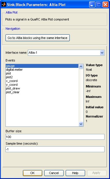
Save the design. Then double-click on the Altia Plot block to open its block parameters dialog. The external connections defined should appear in the list. Click on one of the items in the list to have the block plot the value of that signal.
Installation Requirements
 Please refer to the installation requirements for the
Altia Initialize block.
Please refer to the installation requirements for the
Altia Initialize block.
Input Ports
data
The data to plot on the Quanser Altia Plot component. This signal may be a vector, but the Quanser Altia Plot component must be configured to plot the same number of lines as the signal dimension.
Output Ports
sent
Indicates whether the data was sent to the Quanser Altia Plot component. If the data was sent then this
output is true (1). Otherwise it is false (0).
Parameters and Dialog Box
Go to Altia blocks using the same interface
Opens a dialog that lists all the Altia blocks in the model which are currently using the same interface selected in the Interface name parameter. The dialog may be used to go to another Altia block in the model just by double-clicking on the name of the block in the dialog box.
Interface name
The name of the interface containing the component whose value will be retrieved. Interfaces are configured using the Altia Initialize block. Place an Altia Initialize block in your diagram to add an interface name to the list.
Events
A list of all the events defined as external connections in the Altia design. Select an event from this list as the input of the block.
Buffer size (tunable offline)
The size of the FIFO queue used by this block to buffer events sent to Altia. The buffer size must be greater than zero. Large buffer sizes are recommended to avoid data loss. The block queues events to send to Altia and sends the events from the queue as quickly as it can. If the FIFO queue would overflow, then events are discarded.
Sample time
The sample time of the block. A sample time of 0 indicates that the block will be treated as a continuous time block. A positive sample time indicates that the block is a discrete time block with the given sample time.
A sample time of -1 indicates that the block inherits its sample time from the input. The block inherits the sample time by default.
To set the sample time to the fundamental sampling time of the model, use the qc_get_step_size function, which is a QUARC function that returns the fundamental sampling time of the model. The fundamental sampling time of the model is the sampling time entered in the Fixed step size field of the Solver pane of the Configuration parameters dialog.
Targets
|
Target Name |
Compatible* |
Model Referencing |
Comments |
|---|---|---|---|
|
Yes |
Yes |
||
|
Yes |
Yes |
||
|
Yes |
Yes |
||
|
Yes |
Yes |
||
|
Yes |
Yes |
||
|
Yes |
Yes |
||
|
Yes |
Yes |
||
|
Yes |
Yes |
||
|
Yes |
Yes |
||
|
Yes |
Yes |
||
|
Yes |
Yes |
||
|
Yes |
Yes |
||
|
Yes |
Yes |
||
|
Yes |
Yes |
Last fully supported in QUARC 2018. |
|
|
Rapid Simulation (RSIM) Target |
Yes |
Yes |
|
|
S-Function Target |
No |
N/A |
Old technology. Use model referencing instead. |
|
Normal simulation |
Yes |
Yes |
See Also
Copyright ©2026 Quanser Inc. This page was generated 2026-05-13. Submit feedback to Quanser about this page.
Link to this page.