
Creating Altia GUIs
Altia Design is a powerful user interface design tool. QUARC provides the facilities you need to interact with Altia GUIs from real-time code. Unlike the MATLAB GUIs, MATLAB and Simulink are not required when using Altia GUIs. Standalone GUI applications may developed that communicate with the real-time code completely independent of MATLAB and Simulink. Combined with QUARC's ability to generate production code and configure it to run at boot on any of the supported targets, QuaRc's Altia facilities give you the tools you need to generate complete production systems without writing a single line of code!
This article describes the process of creating and interacting with an Altia GUI, as well as specialized features such as starting and stopping the real-time code from the GUI itself. It is divided into the sections enumerated below. Be sure to read the section on installation requirements because Altia will not work with QUARC unless these requirements have been fulfilled. Click on the link to go a specific section. However, it is recommended that you read this entire article to get the most out of your experience with Altia.
Installation Requirements - Configuring Altia to work with QUARC
 The Altia Design software is not included with QUARC. It must be purchased separately from Altia.
Contact Altia through their web page at https://www.altia.com.
The Altia Design software is not included with QUARC. It must be purchased separately from Altia.
Contact Altia through their web page at https://www.altia.com.
Once Altia has been installed, it must be configured to work with QUARC. This configuration is easy to do, but cannot be omitted. Do not attempt to use any of the Altia blocks provided in QUARC before performing these configuration steps.
To use Altia with QUARC, an environment variable called ALTIAHOME must be created
that points to the installation directory for Altia. For example, Altia may be installed in
the C:\usr\altia803ds folder. To create the environment variable, open the System
properties from Control Panel, choose the Advanced tab, and then click on the Environment Variables button. In
the Environment Variables dialog, click on the New button under the System variables
section and enter ALTIAHOME as the variable name and the installation
directory for Altia as the variable value.
Installation of Altia and setting of the ALTIAHOME environment variable may
require Administrator privileges. Contact your system administrator if necessary to perform
these configuration steps.
 It will be necessary to restart MATLAB after setting the environment variable because applications make a local
copy of environment variables at startup.
It will be necessary to restart MATLAB after setting the environment variable because applications make a local
copy of environment variables at startup.
Where to Begin - Creating an Altia GUI from Simulink
QUARC interacts through with an Altia GUI through a set of blocks specifically designed for that purpose. These blocks are prefixed with the name "Altia" and are located in the QUARC Targets/User Interface/Altia library.
The most important block in this blockset is the Altia Initialize block. The Altia Initialize block must be included in any model that will be interacting with an Altia GUI. It establishes the connection to the Altia GUI and is the primary interface for creating and editing an Altia GUI from Simulink.
To begin using Altia with QUARC, drag an Altia Initialize block into your model. Then open the block properties of the Altia Initialize block by double-clicking on the block. A dialog box similar to the one shown below will be opened.
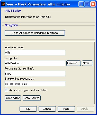
The Interface name field defines the name for the Altia interface. The name is arbitrary but must be unique throughout the model. This name is used by the other Altia blocks to refer to the Altia interface. Use of an interface name makes it easy to associate Altia blocks with an interface without having to wire them all together.
To create a new Altia GUI for use with QUARC, enter the name of the Altia Design file in the
Design file parameter. Then click on the
button. The button creates a new Altia design of the given
name in the current MATLAB directory and opens that design in the Altia Design editor. Altia Design files
have the .dsn extension. Be sure to use a different design file for each
Altia Initialize block in your diagram if you are supporting multiple
interfaces.
You may now proceed to design your GUI in Altia Design. The following subsections describe how to connect Altia components, such as knobs, sliders, meters and plots to your model.
Getting Values - Knobs and other inputs
User interfaces are often used to change parameters in the model, such as the commanded position, or speed or controller gains. Altia components such as knobs and sliders may be used for this purpose. This section does not provide a tutorial on Altia because a full set of documentation, videos and tutorials are provided with the Altia product line. Instead, this section focuses exclusively on how to make the connection between a component, such as a knob, in Altia and the Simulink model in QUARC.
Knobs, sliders and other input components in Altia generate events. Events have an associated name and value. For example, the knob in Altia generates an event whose value represents the position of the knob. To make these events available to QUARC, you must define "external input connections" in the Altia design for all the signals you wish to make available. External input connections are created in Altia by selecting from the menu. The External Connections dialog shown below will appear:
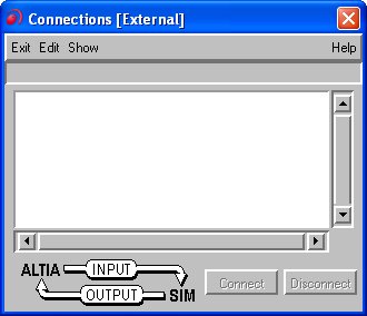
Select from the menu of this dialog. Enter a name for the connection and an animation name. The animation name is the name that will be visible in QUARC. It must be unique throughout the Altia design. Choose the radio button to indicate that this connection will be an input i.e. a signal sent from Altia to the real-time code or "SIM" as it is indicated in the dialog.
Once the external connections have been defined, you need to connect them to an Altia GUI component for them to manipulate the Altia GUI. Keep the External Connections dialog open. Select the item from the menu. The dialog shown below will appear.
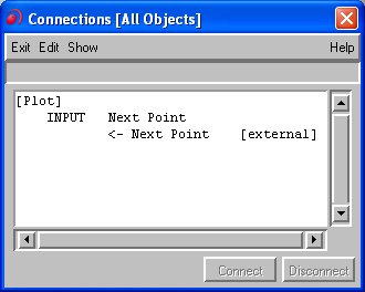
Select one of the component's output signals in the Connections dialog. Also select the corresponding input connection in the External Connections dialog. The button should become enabled. Click on the button to establish the link between the external connection visible to Simulink and the component.
Save the design. Failure to save the design after defining the external input
connections will result in the animation names not being visible in QUARC.
To access these external connections in QUARC, place an Altia Get Value block in your model. Double-click on the Altia Get Value block to open its parameters dialog. This dialog is illustrated below.
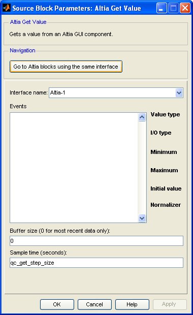
Select the name of the interface defined by the Altia Initialize block in the Interface name field. Note that an Altia Initialize block must be present in the diagram.
The external input connections defined in the Altia design should appear in the list. Click on one of the items in the list to have the block get the value of that signal. The value of this signal will appear at the output of the Altia Get Value block.
Note that the block does not wait for the value to change so it will not delay execution of the model. Instead, Altia Get Value block provides a new output that indicates whenever a new value is received. This boolean output may be used to execute an Enabled Subsystem whenever a new value is received. However, the block always outputs the most recently received value if the value has not changed so it is typically unnecessary to use the new output.
Communication with the Altia GUI is actually done in a separate thread. This thread stores the data in a FIFO queue as new values are received. The Altia Get Value block retrieves the values from that queue. The Buffer size parameter allows you to control the size of that FIFO queue. If the queue overflows because values are received faster than the Altia Get Value block removes them from the queue then values are discarded. The Altia Get Value block removes one value from the FIFO each time it executes, so the rate at which values are retrieved from the queue is determined by the sample time of the block.
If the buffer size is set to zero then the thread does not use a FIFO queue. Instead, it simply supplies the most recently received value to the Altia Get Value block. The default buffer size is zero because the most recent value is the one typically required. The FIFO queue, however, is useful when all the values need to be retrieved.
Setting Values - Meters and other outputs
A user interface would not be complete without the ability to monitor signals in the real-time code. Altia components such as meters and text readouts may be used for this purpose. This section does not provide a tutorial on Altia because a full set of documentation, videos and tutorials are provided with the Altia product line. Instead, this section focuses exclusively on how to make the connection between a component, such as a meter, in Altia and the Simulink model in QUARC.
Meters and other output components in Altia are driven by events. Events have an associated name and value. For example, the position of the needle in a meter is controlled by an event, in which the value of the event determines the needle location. To access these events in QUARC, you must define "external output connections" in the Altia design for all the signals you wish to make accessable. External output connections are created in Altia by selecting from the menu. The External Connections dialog shown below will appear:
Select from the menu of this dialog. Enter a name for the connection and an animation name. The animation name is the name that will appear in QUARC. It must be unique throughout the Altia design. Choose the radio button to indicate that this connection will be an output i.e. a signal sent to Altia from the real-time code or "SIM" as it is indicated in the dialog.
Once the external output connections have been defined, you need to connect them to an Altia GUI component for them to manipulate the Altia GUI. Keep the External Connections dialog open. Select the item from the menu. The dialog shown below will appear.
Select one of the component's input signals in the Connections dialog. Also select the corresponding output connection in the External Connections dialog. The Connect button should become enabled. Click on the button to establish the link between the external connection visible to Simulink and the component.
Save the design. Failure to save the design after defining the external output
connections will result in the animation names not being visible in QUARC.
To access these external connections in QUARC, place an Altia Set Value block in your model. Double-click on the Altia Set Value block to open its parameters dialog. This dialog is illustrated below.
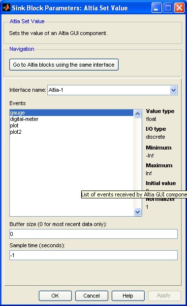
Select the name of the interface defined by the Altia Initialize block in the Interface name field. Note that an Altia Initialize block must be present in the diagram.
The external output connections defined in the Altia design should appear in the list. Click on one of the items in the list to have the block set the value of that signal. The input to the block will be used to drive the value of the Altia event.
Note that the block does not wait for the value to be sent to the Altia GUI so it will not delay execution of the model. Instead, Altia Set Value block provides a sent output that indicates whenever the value has been sent. This boolean output may be used to execute an Enabled Subsystem whenever a value is sent. However, it is typically unnecessary to use the sent output.
Communication with the Altia GUI is actually done in a separate thread. The Altia Set Value block stores its input in a FIFO queue. The thread retrieves the values from the FIFO queue and transmits them to the Altia GUI. The Buffer size parameter allows you to control the size of that FIFO queue. If the queue overflows because values are queued faster than the thread can send them to Altia new values are discarded until room is available in the queue. The Altia Set Value block adds one value to the FIFO each time it executes, so the rate at which values are stored in the queue is determined by the sample time of the block.
Communication with the Altia GUI is actually done in a separate thread. The Altia Set Value block stores its input in a FIFO queue. The thread retrieves the values from the FIFO queue and transmits them to the Altia GUI. The Buffer size parameter allows you to control the size of that FIFO queue. If the queue overflows because values are queued faster than the thread can send them to Altia new values are discarded until room is available in the queue. The Altia Set Value block adds one value to the FIFO each time it executes, so the rate at which values are stored in the queue is determined by the sample time of the block.
If the buffer size is set to zero then the Altia Set Value block does not use a FIFO queue. Instead, it simply records the most recent value to the communications thread. The default buffer size is zero because most Altia GUI components display the instantaneous value of an event so only the most recent value is required. The FIFO queue, however, is useful when all the values need to be transmitted.
Plotting - the Quanser Plot Library for Altia
The plotting components supplied with Altia are rather primitive. They are designed to plot the value of an event but do not plot it versus time. Instead, the x-axis is advanced each time the event occurs. Some advanced Altia programming is required to get the plots to behave like a normal x versus time plot. Fortunately, Quanser has done the work for you and created the Quanser Altia Plot library!
The Quanser Altia Plot component is installed with QUARC and is located under the
QUARC tree under altia\models in the plots.dsn library.
Open the library from Altia using the button
and browse to the location of the plots.dsn library. For example,
if QUARC is installed in the C:\Program Files\Quanser\QUARC directory,
then the Quanser Altia Plot components are found in the file C:\Program Files\Quanser\QUARC\altia\models\plots.dsn.
Click the following link to browse to the
models
MATLAB Command Line
Click to copy the following command line to the clipboard. Then paste it in the MATLAB Command Window:
dos(['explorer ', fullfile(getenv('QUARC_DIR'), 'altia', 'models')]);
folder.
Drag a Plot component into your Altia GUI from the plots.dsn library.
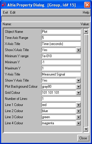
Double-click on the Plot component to open its properties and set the number of
lines to the number of traces you wish to plot. Try to limit the number of traces
plotted since the performance is better with fewer traces. Choose the time axis and Y-axis ranges as well. Note that
changing the Y-Axis Minimum property does not
change the Y-axis range. The Y-axis range does not change until the Y-Axis Maximum
is also modified. The Plot component may modify the range slightly to ensure that the grid lines are aligned on "nice" numbers.
Quanser's Altia Plot component is driven by events, just like any other Altia component. Events have an associated name
and value. Even though the Plot component has a large number of events, the only event that should be used is
the nextpoint event. To access this event in QUARC, you must define an "external output connection"
in the Altia design for this signal be accessable. External output connections are created in Altia by
selecting from the menu. The External
Connections dialog shown below will appear:
Select from the menu of this dialog. Enter a name for the connection and an animation name. The animation name is the name that will appear in the Events listbox. It must be unique throughout the Altia design. Choose the radio button to indicate that this connection will be an output i.e. a signal sent to Altia from the real-time code or "SIM" as it is indicated in the dialog.
Once the external connection has been defined, you need to connect it to a Quanser Altia Plot component for it to plot the signal. Keep the External Connections dialog open. Select the item from the menu. The dialog shown below will appear.
Select the Plot component's nextpoint event in the Connections dialog. Also select
the corresponding output connection in the External Connections dialog. The
button should become enabled. Click on the button to establish the link between the
external connection visible to Simulink and the component.
Save the design. Failure to save the design after defining the external output
connections will result in the animation names not being visible in QUARC.
Now place an Altia Plot block in your model. Only an Altia Plot block may be used to drive a Quanser Altia Plot component. Double-click on the Altia Plot block to open its parameters dialog. This dialog is illustrated below.
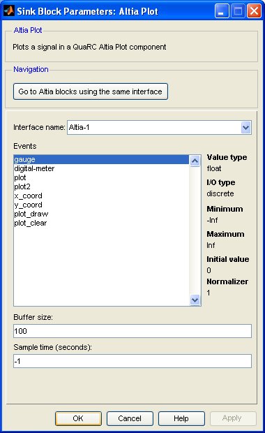
Select the name of the interface defined by the Altia Initialize block in the Interface name field. Note that an Altia Initialize block must be present in the diagram.
The external output connections defined in the Altia design should appear in the list. Click on one of the items in the list to have the block set the value of that signal. Only an event associated with a Quanser Altia Plot component should be selected. The input to the block will be graphed on the Plot component.
Note that the block does not wait for the value to be sent to the Altia GUI so it will not delay execution of the model. Instead, Altia Set Value block provides a sent output that indicates whenever the value has been sent. This boolean output may be used to execute an Enabled Subsystem whenever a value is sent. However, it is typically unnecessary to use the sent output.
Communication with the Altia GUI is actually done in a separate thread. The Altia Plot block stores its input in a FIFO queue. The thread retrieves the values from the FIFO queue and transmits them to the Altia GUI. The Buffer size parameter allows you to control the size of that FIFO queue. If the queue overflows because values are queued faster than the thread can send them to Altia new values are discarded until room is available in the queue. The Altia Plot block adds one value to the FIFO each time it executes, so the rate at which values are stored in the queue is determined by the sample time of the block.
Unlike the other Altia blocks, the buffer size for the Altia Plot block should not be set to zero because otherwise the time history of the signal may not be plotted.
Controlling Models - Starting and stopping models from Altia
QUARC provides all the facilities you need to make a production-ready user interface with Altia. The command-line tools supplied with QUARC allow you to control real-time code from a host PC using batch scripts or Windows Explorer. In particular, the quarc_run command may be invoked from an Altia GUI component in order to start and stop the real-time code, right from the user interface! Since the Altia Initialize block maintains a persistent connection to the Altia GUI it does not matter whether the real-time code or the user interface is started first. In fact, you can even start and stop the model repeatedly with the GUI open and it will always reconnect each time.
Starting a Model
To start the real-time code from an Altia component, such as a push button or toggle button, set the value of the
altiaStartProgram animation to a string containing the following command:
quarc_run -l mymodel
in the Control Editor. For example, this command might be invoked each time a button is pressed to start
the model. Replace mymodel with the name of your Simulink model. This command assumes that the
code has already been downloaded and that the target system is the same computer as the host PC.
To start the model on a remote target system, use a command of the form:
quarc_run -t tcpip://remotehost:17000 -l mymodel
Replace the target URI, tcpip://remotehost:17000, with an appropriate URI for your remote target system. See the section on Communicating with the Target for more information on target URIs and communicating with remote targets.
You can specify the current directory that will be used by the real-time code using the -d argument
to the model. The -d option must follow the model name. For example,
quarc_run -l mymodel -d /tmp
Refer to the Command Line Tools
documentation for more information about the quarc_run command and its various options.
Stopping a Model
To stop the real-time code from an Altia component, such as a push button or toggle button, set the value of the
altiaStartProgram animation to a string containing the following command:
quarc_run -q mymodel
in the Control Editor. For example, this command might be invoked each time a button is pressed to stop
the model. Replace mymodel with the name of your Simulink model. This command assumes that the
code is already running and that the target system is the same computer as the host PC.
To stop the model on a remote target system, use a command of the form:
quarc_run -t tcpip://remotehost:17000 -q mymodel
Replace the target URI, tcpip://remotehost:17000, with an appropriate URI for your remote target system. See the section on Communicating with the Target for more information on target URIs and communicating with remote targets.
Deployment - Running your GUI
Once your GUI has been designed and is ready for deployment, you have two options. If you have purchased the Deep Screen product from Altia then you can generate a standalone executable from your Altia design. That executable may then be run directly in your production system.
If you do not have Deep Screen, you can still execute your GUI from a batch script using the Altia Runtime. An Altia design is loaded by using a command of the form:
altiart -lan -port "<port_name>" -file "<design_file>"
Substitute <port_name> for the port name configured in the Port name parameter of the Altia Initialize block in your model. The default port is 5100. Substitute the name of your design file for the <design_file> argument. For example, "AltiaDesign.dsn". Be sure to keep the quotes in order to handle spaces in the filename.
Copyright ©2026 Quanser Inc. This page was generated 2026-05-13. Submit feedback to Quanser about this page.
Link to this page.