
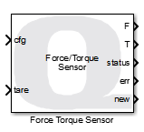
Force Torque Sensor
Reads a force/torque sensor.
Library
QUARC Targets/Devices/Third-Party/Sensors MATLAB Command Line Click to copy the following command line to the clipboard. Then paste it in the MATLAB Command Window: qc_open_library('quarc_library/Devices/Third-Party/Sensors')
Description
The Force Torque Sensor block reads a force/torque sensor like the ATI Net F/T series. The output of the block is the forces and torques in SI units of N and N-m respectively.
The Force Torque Sensor block also outputs a new output indicating whether the current output is new data or not. When new is false, the force and torque outputs should be ignored, although the last valid values will be held at the outputs.
It also produces a status output indicating the status of the sensor. The status is a bit mask which indicates any error conditions. For the ATI Net F/T sensors, these bits are defined as:
|
Bit |
Mask |
Description |
|---|---|---|
|
0 |
0x00000001 |
Reserved |
|
1 |
0x00000002 |
HTTP protocol failure |
|
2 |
0x00000004 |
Internal temperature error |
|
3 |
0x00000008 |
Reference voltage or power monitoring error |
|
4 |
0x00000010 |
Serial link data unavailable |
|
5 |
0x00000020 |
Analog board power supply too low |
|
6 |
0x00000040 |
Analog board power supply too high |
|
7 |
0x00000080 |
Artificial analog ground out of range |
|
8 |
0x00000100 |
Insufficient straing gauge excitation current |
|
9 |
0x00000200 |
Excessive strain gauge excitation current |
|
10 |
0x00000400 |
Analog board watchdog timeout error |
|
11 |
0x00000800 |
Serial flash SPI communications failure |
|
12 |
0x00001000 |
Serial EEPROM I2C communications failure |
|
13 |
0x00002000 |
Stack check error |
|
14 |
0x00004000 |
Watchdog timeout error |
|
15 |
0x00008000 |
Reserved |
|
16 |
0x00010000 |
Threshold latched (not an error) |
|
17 |
0x00020000 |
Transducer saturation or A/D operation error |
|
18 |
0x00040000 |
DeviceNet compatibility mode protocol failure |
|
19 |
0x00080000 |
EtherNet/IP protocol failure |
|
20 |
0x00100000 |
RDT communication error |
|
21 |
0x00200000 |
CAN bus communication error |
|
22 |
0x00400000 |
Network communication failure |
|
23 |
0x00800000 |
Configuration settings incompatible with transducer calibration |
|
24 |
0x01000000 |
Settings validation error |
|
25 |
0x02000000 |
Sensor halted due to configuration errors |
|
26 |
0x04000000 |
Program memory verification error |
|
27 |
0x08000000 |
Serial link communication error |
|
28 |
0x10000000 |
Analog board error |
|
29 |
0x20000000 |
Digital board error |
|
30 |
0x40000000 |
CPU or RAM error |
|
31 |
0x80000000 |
Set if any error condition exists |
For the ATI Net F/T sensor a status value of zero indicates that the sensor is healthy.
The inputs to the block may be used to change sensor configurations or to tare the load, which means zeroing the output in software by using a snapshot of the current values as a negative bias. Whenever the cfg input changes, the new configuration is selected. Similarly, whenever the tare input rises and crosses zero (or starts at zero), then the Force Torque Sensor block tares the load and the force/torque outputs will be zeroed instantaneously.
Input Ports
cfg
The active sensor configuration to use, when the sensor supports multiple configurations. Values
outside the valid range will be saturated to a valid configuration number. Configuration numbers
are zero-based, so the first configuration is numbered 0.
Whenever the cfg input changes, the new configuration will be selected. Changing configurations is generally a slow process involving stopping and restarting measurements. Hence it should only be done when it is safe to do so.
tare
When a rising edge is seen on this input, crossing zero or starting at zero, then the Force Torque Sensor block zeroes the outputs in software. Hence, the force and torque outputs will instantaneously jump to zero and will use the new bias until the sensor is tared again.
addr
A string specifying the address of the sensor. The string must be a null-terminated
vector of characters represented as a vector of uint8 quantities. This string is typically provided
either directly or indirectly by a Model Argument
block or String Constant block. The input may
be fixed-sized or variable-sized.
This input is only available if the Address source parameter is
set to External input port. Refer to the documentation below on the
Address source parameter for details.
Output Ports
F
The measured forces as a double 3-vector in Newtons.
T
The measured torques as a double 3-vector in Newton-meters.
status
A 32-bit bitmask as a signed 32-bit integer where each bit indicates a particular status condition. See the table in the description for details. For the ATI Net F/T sensors, the most-significant bit is set if any error condition has occurred, in which case this output will be negative.
err
An int32 error code indicating the result of the operation. If the sensor is sending data then this output will be 1. If it is not sending data then it will be zero or a negative error code. See Error Codes for the different error codes and their values. Use the Compare to Error block rather than the error code itself to check for specific error codes.
new
Indicates whether the data at the outputs is new. Since the block does not wait for the measurement to be taken, this output may be used to determine when a new measurement has been taken. If the measurement is not new, the force/torque outputs will hold their prior values.
Data Type Support
This block supports outputs of type double. The inputs may be any of the standard Simulink data types.
Parameters and Dialog Box
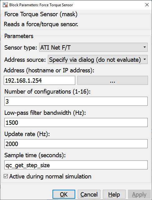
Sensor type
Determines the type of force/torque sensor to read. Only the sensors in the list are supported. The Address parameter determines how the block communicates with the selected sensor.
Address source
Indicates whether the address should be determined from the dialog parameters or an
input port. If this field is set to Specify via dialog (do not evaluate) then
the address is specified via the Address
parameter. In this case, the address is not evaluated as a MATLAB expression but is
interpreted as a literal string. However, format specifiers are recognized. Refer
to qc_perform_substitutions
for a list of the format specifiers available.
If this field is set to Specify via dialog (evaluate) then the address is also specified
via the Address parameter. However, in this case, the address is evaluated
as a MATLAB expression. This option is convenient for using a variable in the MATLAB workspace
for the address.
If this field is set to External input port then the Address
parameter is ignored and an extra input port is provided which determines the address.
Address (tunable offline)
The hostname or IP address of the sensor, for those sensors that support Ethernet communications. A URI parameter is not provided in this case because the sensor may require multiple protocols. For example, the ATI Net F/T sensor uses three different protocols to provide the functionality of this block: Raw Data Transfer (RDT) over UDP port 49152, TCP/IP over port 49151 and HTTP over port 80.
The browse button next to the Address field may be used to scan the network for sensors. A list will be presented if any sensors are found and the sensor's IP address may be selected from the list.
Number of configurations (tunable offline)
The number of configurations being used in the sensor. The cfg input will be saturated according to this parameter.
Low-pass filter bandwidth (Hz) (tunable offline)
The bandwidth of the low-pass filter to use for filtering the raw sensor measurements. The filtering is done in the sensor itself. The actual bandwidth may not match the given value exactly, but will be rounded to the nearest setting supported by the sensor. For the ATI Net F/T sensor valid values range from 5 Hz to 3000 Hz. Use a value of zero to bypass the low-pass filter (no filter).
Update rate (Hz) (tunable offline)
The rate at which the sensor provides measurements. The internal sampling rate of the sensor may be much higher. This parameter defines the rate for the communication channel. For the ATI Net F/T sensors, this value may go as high as 7000 Hz. However, be aware that this setting may use significant network bandwidth.
Sample time (second)
The sampling period (in seconds) at which the sensor data are output from the Force Torque Sensor block. A sample time of 0 indicates that the block will be treated as a continuous time block. A positive sample time indicates that the block is a discrete time block with the given sample time.
A sample time of -1 indicates that the block inherits its sample time. Since this is a source block, only inherent the sample time when it is placed in a conditionally executed subsystem, like a Triggered or Enabled Subsystem, or in a referenced model.
The default sample time is set to qc_get_step_size, which is a QUARC function that returns the fundamental sampling time of the model. Hence, the default sample time is a discrete sample time with the same sampling time as the fixed step size of the model.
Active during normal simulation
If this option is checked then the block will attempt to read from the sensor in normal simulation. In this case, the sensor must be connected to the host PC rather than the target.
Targets
|
Target Name |
Compatible* |
Model Referencing |
Comments |
|---|---|---|---|
|
Yes |
Yes |
||
|
Yes |
Yes |
||
|
Yes |
Yes |
||
|
Yes |
Yes |
||
|
Yes |
Yes |
||
|
Yes |
Yes |
||
|
Yes |
Yes |
||
|
Yes |
Yes |
||
|
Yes |
Yes |
||
|
Yes |
Yes |
||
|
Yes |
Yes |
||
|
Yes |
Yes |
||
|
Yes |
Yes |
||
|
Yes |
Yes |
Last fully supported in QUARC 2018. |
|
|
Rapid Simulation (RSIM) Target |
Yes |
Yes |
|
|
S-Function Target |
No |
N/A |
Old technology. Use model referencing instead. |
|
Normal simulation |
Yes |
Yes |
Copyright ©2026 Quanser Inc. This page was generated 2026-05-13. Submit feedback to Quanser about this page.
Link to this page.