
HIL Read Timebase
Reads the specified channels at the sampling rate of the model and acts as a timebase for the model.
Library
QUARC Targets/Data Acquisition/Generic/Timebases MATLAB Command Line Click to copy the following command line to the clipboard. Then paste it in the MATLAB Command Window: qc_open_library('quarc_library/Data Acquisition/Generic/Timebases')
Description
The HIL Read Timebase block reads the specified channels at every sampling instant. The timebase for the model is provided by the block itself. Only one HIL Timebase block may appear in the model. Multiple timebases for a model are not supported. This block can read more than one type of channel at the same time. Using this block is more efficient than using separate blocks for each channel type when more than one type of channel is being read.
The other outputs of the block will be assigned appropriate SI units, if possible. When the other outputs are a single vector then units are only assigned if every element would have the same units.
 All the channels which will be used as digital inputs must be entered
in the Digital input channels field of the
Digital Inputs pane in the HIL Initialize
block's parameters dialog. Doing so ensures that those channels will be configured as inputs when using a card for which
the digital I/O lines are programmable as inputs or outputs. Failure to configure these channels
in the Digital input channels field as inputs may result in the
HIL Read Timebase block failing to read those inputs.
All the channels which will be used as digital inputs must be entered
in the Digital input channels field of the
Digital Inputs pane in the HIL Initialize
block's parameters dialog. Doing so ensures that those channels will be configured as inputs when using a card for which
the digital I/O lines are programmable as inputs or outputs. Failure to configure these channels
in the Digital input channels field as inputs may result in the
HIL Read Timebase block failing to read those inputs.
Input Ports
This block has no input ports.
Output Ports
The number of output ports depends on the Vector output parameter. If this option is off then there is one output port for each channel and each port outputs the value read from the corresponding channel. If this option is on then there is one output port for each channel type for which channels are defined, and each output is a vector containing the values read from the channels specified in the corresponding Channels parameter for that channel type. If the option is grouped, then there will be an output port for each consecutive group of channels within each channel type. Refer to the documentation on the Vector output parameter below for more details.
For scalar outputs, the signal will have units commensurate with the corresponding channel. For vector outputs, the signal will only have units if all the channels corresponding to each element of the vector have the same units.
Data Type Support
The HIL Read Timebase block outputs signals of type double
for the analog and other channels, it outputs signals of type int32 or double
for the encoder channels and it outputs any of the built-in Simulink datatypes except fixed point for the
digital channels. See the Signal Data Types pane below for information on
how the output data type is determined.
Parameters and Dialog Box
Individual Panes
Main Pane
The Main pane of the dialog appears as follows:
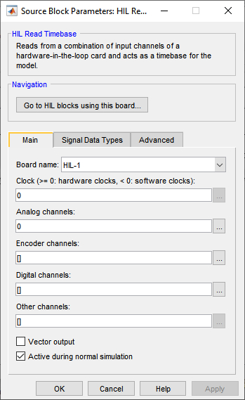
Board Name
The name of the board whose channels will be read. Boards are configured using the HIL Initialize block. Place an HIL Initialize block in your diagram to add a board name to the list.
Clock (tunable offline)
The clock to use as a basis for the timebase. In general, both system clocks and hardware clocks specific to the board are supported. This parameter must be a scalar. A positive value indicates a hardware clock. For example, enter 0 for HARDWARE_CLOCK_0, 1 for HARDWARE_CLOCK_1, etc. The number of hardware clocks available depends on the board selected. A negative value indicates a system clock. For example, enter -1 for SYSTEM_CLOCK_1, -2 for SYSTEM_CLOCK_2, etc. The sampling rate for the block is determined by the fundamental sampling rate of the model, which is the sampling time entered in the Fixed step size field of the Solver pane of the Configuration parameters. Refer to Clocks for more information.
Select a board type from the list for board-specific details:
Analog channels (tunable offline)
The analog channels to read. The number of analog channels available depends on the board selected. Refer to Channels for more information. The output is the voltages read from the analog inputs.
Select a board type from the list for board-specific details:
Encoder channels (tunable offline)
The encoder channels to read. The number of channels available depends on the board selected. Refer to Channels for more information. The output is the count values read from the encoder counters.
Select a board type from the list for board-specific details:
Digital channels (tunable offline)
The digital channels to read. The number of channels available depends on the board selected. Refer to Channels for more information. The output is the states read from the digital inputs.
Select a board type from the list for board-specific details:
Other channels (tunable offline)
The other channels to read. The number of channels available depends on the board selected. Refer to Other Channels for more information about other channels in QUARC. The output is the values read from the other inputs.
Most boards do not support other channels. Select a board type from the list for board-specific details:
Vector output
If this option is set to on then the block will have a vector output for each type of channel for which channels are defined, with one element in the vector for each channel of that type. The values read from each channel will appear in the vector in the same order as the corresponding Channels parameter for that type.
For example, if analog channels 3 and 4 are selected, then the first output port will be a 2-vector with the first element containing the voltages read from analog input 3 and the second element containing the voltages read from analog input 4. Each output port will be labeled with the prefix indicating the type of channel represented by that output port. Refer to the table below for an explanation of the prefixes used.
If this option is set to grouped then the block will have one output for each consecutive group of channels within each channel type. The output ports will appear in the same order as the channels in the corresponding Channels parameter for that type. Each port will be labeled with the prefix indicating the type of channel followed by the first channel in the corresponding group. Refer to the table below for an explanation of the prefixes used. Note that the Channels parameters will not be tunable offline when the outputs are grouped because the channel numbers themselves determine the number of outputs.
To force grouped channels that are naturally consecutive to appear as separate outputs, simply change the order so that they are not consecutive. For example, a channel selection of [0, 1, 2] will appear as a single vector, but a channel selection of [2, 1, 0] will appear as three separate outputs, the first for channel 2, the next for channel 1 and the last for channel 0. Finally, a channel selection of [2, 0, 1] will appear as a scalar output for channel 2 and a 2-vector output for channels 0 and 1.
If this option is set to off then the block will have one output for each channel. The output ports will appear in the same order as the channels in the Analog channels, Encoder channels, Digital channels amd Other channels parameters. Each port will be labeled with a prefix indicating the channel type and the corresponding channel number. The prefixes are:
|
|
|
|---|---|
|
|
analog |
|
|
encoder |
|
|
digital |
|
|
other |
Port labels
This parameter allows the labels on the port to be changed to reflect the channel numbers or the signal names, when signal names are available. The table below enumerates the different display options. This parameter has no effect on generated code.
|
Option |
Description |
|---|---|
|
channel numbers |
Displays a letter from the table of prefixes above indicating the type of channel followed by the channel number. |
|
signal names |
Displays the full signal name for each port, if available. Otherwise the channel number is displayed. |
|
short names |
Displays a shortened version of the signal name for each port, if available. Otherwise the channel number is displayed. Each word in the signal name is typically shortened to no more than four characters. |
|
abbreviated names |
Displays an abbreviated version of the signal name for each port, if available. Otherwise the channel number is displayed. The abbreviated version is the first letter from each word in the signal name. Any parentheses or brackets are removed. |
Signal Data Types Pane
The Signal Data Types pane of the dialog appears as follows:
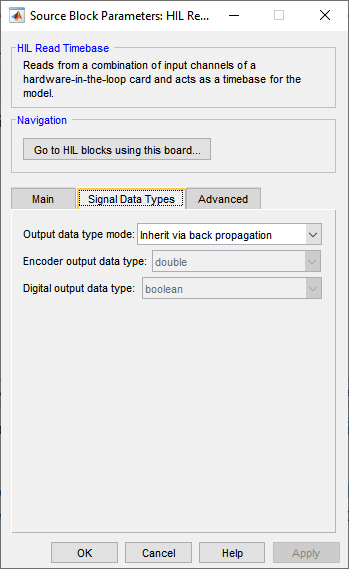
Output data type mode
Sets the data type of the output to be inherited by back propagation or to be specified
explicitly in the dialog. This parameter only affects the encoder and digital channels.
The analog and other channels are always double.
If back propagation is selected then the data type of the encoder and digital outputs
will be determined by the blocks to which these outputs are connected. If an encoder
output is not connected or it is connected to a block which supports multiple datatypes,
then the output data type will be double. If a digital
output is not connected or it is connected to a block which supports multiple datatypes,
then the output data type will be boolean.
Otherwise the data type of the encoder outputs can be specified explicitly using the Encoder output data type parameter and the data type of the digital outputs can be specified explicitly using the Digital output data type parameter.
Encoder output data type
Sets the data type of the encoder outputs explicitly.
Digital output data type
Sets the data type of the digital outputs explicitly.
Advanced Pane
The Advanced pane of the dialog appears as follows:
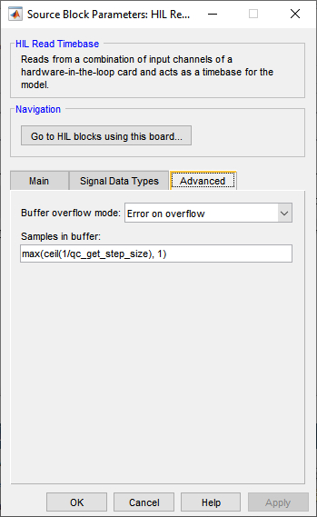
Buffer overflow mode (tunable offline)
The buffer overflow mode determines what happens when the task buffer overflows. The default behaviour is to stop the model with an error because buffer overflow means that the foreground task has not been able to keep up with the timebase from the hardware. The Error on overflow option results in this behaviour.
The Overwrite on overflow option causes new samples to overwrite the oldest samples in the buffer when the buffer would overflow. In this case, these oldest samples will be lost, but the model will continue to run.
The Discard on overflow option discards new samples if there is no room in the task buffer. In this case, the older samples are preserved and will be output from the block in proper sequence. New samples are lost, but the model will continue to run.
The Wait on overflow option is only used with simulated cards. Simulated cards can be implemented in a separate model using the HIL Simulation block. When the Wait on overflow option is specified and the task buffer is full, it causes the model simulating the card to block until the model containing the HIL Read Timebase block removes a sample from the task buffer, making room for the new sample. This allows the two models to be synchronized and is generally only useful in normal simulation, where sample time performance is poor. If this option is specified then a value of 1 is recommended for the Samples in buffer option. More complete synchronization is provided by the Synchronize option, described below, which is recommended when using simulated cards.
The Synchronize option is also only used with simulated cards. Simulated cards can be implemented in a separate model using the HIL Simulation block. When the Synchronize option is specified it causes the model to synchronize with the model simulating the card. This is generally only useful in normal simulation, where sample time performance is poor.
Samples in buffer (tunable offline)
The number of samples in the task buffer. Timebase blocks are implemented as HIL tasks. Tasks operate as separate "threads" in the driver for the card that read data from the hardware at a given rate. The data read is stored in the task buffer. If the task buffer overflows then the block typically stops the model with an error, although this behaviour can be changed using the Buffer overflow mode parameter. Each time the block executes, it reads one sample from the task buffer. If there is no data in the task buffer then it waits until a sample arrives. Hence, the block synchronizes the diagram to the sampling rate of the task. Making the number of samples in the task buffer greater than one allows the sampling rate to temporarily exceed one sampling interval, which is useful for normal simulation.
Some boards restrict the number of samples that may be specified. Select a board type from the list for board-specific details:
Targets
|
Target Name |
Compatible* |
Model Referencing |
Comments |
|---|---|---|---|
|
Yes |
Not supported in a referenced model. Use in top-level model only. |
Only one HIL Timebase block is allowed in a model. |
|
|
Yes |
Not supported in a referenced model. Use in top-level model only. |
Only one HIL Timebase block is allowed in a model. |
|
|
Yes |
Yes |
||
|
Yes |
Yes |
||
|
Yes |
Yes |
||
|
Yes |
Yes |
||
|
Yes |
Yes |
||
|
Yes |
Yes |
||
|
Yes |
Yes |
||
|
Yes |
Yes |
||
|
Yes |
Yes |
||
|
Yes |
Yes |
||
|
No |
No |
Not supported. |
|
|
Yes |
Not supported in a referenced model. Use in top-level model only. |
Last fully supported in QUARC 2018. Only one HIL Timebase block is allowed in a model. |
|
|
Rapid Simulation (RSIM) Target |
Yes |
Yes |
Only one HIL Timebase block is allowed in a model. |
|
S-Function Target |
No |
N/A |
Old technology. Use model referencing instead. |
|
Normal simulation |
Yes |
Yes |
Due to safety and liability concerns, the hardware may not be accessed during normal simulation. |
See Also
Copyright ©2026 Quanser Inc. This page was generated 2026-05-13. Submit feedback to Quanser about this page.
Link to this page.