
Quanser QArm
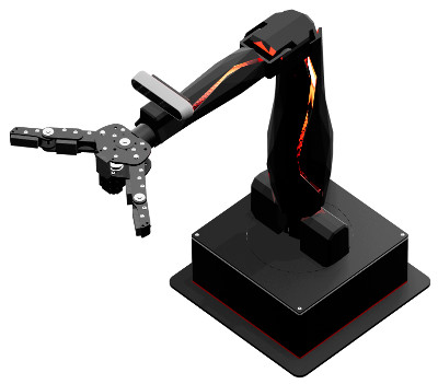
The Quanser QArm is a 4 DOF serial robotic manipulator with a tendon-based two-stage gripper and an RGBD camera, designed specifically for modern engineering education. For more information, visit the Quanser website for the QArm.
The QUARC driver name for this card is qarm_usb.
To select the Quanser QArm HIL board, select the QUARC qarm_usb board type from the drop-down list on the Main tab of the HIL Initialize block.
The Quanser QArm I/O channels are described below.
Communications
The communications ports provided on the Quanser QArm End Effector board can be utilized through the QUARC Communications blockset and the Quanser Stream API (see QUARC Communications Protocols).
SPI
For SPI communications, a sample URI for communications would be:
spi-qarm-usb://localhost:0?baud='1000000',word='8',polarity='off',phase='off',lsb='off',frame='0'
where a frame option of 0 selects the hardware SPI SS line to frame the SPI bus transaction (omit this option if no SS line is required). The actual baud rate may be one of the following:
The QUARC Communications driver will select the actual baud rate closest to the baud rate specified in the URI. On the Quanser QArm, the word length may range from 4 to 16 bits inclusive. All lsb, polarity and phase options are supported. The SPI lines are shared with digital I/O lines 14, 15, 16 and 17.
I2C
For I2C communications, a sample URI for communications would be:
i2c-qarm-usb://localhost:0?baud='100000',address=0x69
where the address option specifies the I2C slave address (not including the R/W bit). 10-bit addressing is also supported. Baud rates between 10 kHz and 400 kHz may be specified. A rise and fall time of 125 ns are assumed when configuring the internal I2C timing registers. The I2C lines are shared with digital I/O lines 10 and 11.
Serial
For serial communications, a sample URI for communications would be:
serial-qarm-usb://localhost:0?baud='115200',parity='none',stop='1'
where the baud option specifies the serial baud rate from 1100 Baud to 9 MBaud. Baud rates less than or equal to 4.5 MBaud yield better oversampling performance. Only 1/2 stop bits, odd/even/no parity and 8-bit word lengths are supported on the Quanser QArm. Flow control is not supported. The I2C lines are shared with digital I/O lines 2 and 3.
| A digital line cannot be used as a GPIO and a communication peripheral at the same time. |
Clocks
There are currently no configuration options for the Quanser QArm clocks.
Analog Inputs
The Quanser QArm currently supports 10 analog inputs.
The first five analog inputs measure the voltage on the respective Analog Input pins found on the End Effector board's User Connector 1 (labelled AX, where X = {0,1,2,3,4}). The analog input range for these channels is 0 to +5V and is not configurable. Exceeding this range may damage the board.
The last five analog inputs measure the current to each servo motor joint in Amperes. Refer to the table below for a list of all analog input channels and their respective maximum ranges:
|
Channel |
Description |
Range |
|---|---|---|
|
0 |
User Analog Input 0 |
0V to +5V |
|
1 |
User Analog Input 1 |
0V to +5V |
|
2 |
User Analog Input 2 |
0V to +5V |
|
3 |
User Analog Input 3 |
0V to +5V |
|
4 |
User Analog Input 4 |
0V to +5V |
|
5 |
Present Current - Yaw Joint |
±4.4A |
|
6 |
Present Current - Shoulder Joint |
±8.8A |
|
7 |
Present Current - Elbow Joint |
±4.4A |
|
8 |
Present Current - Wrist Joint |
±2.3A |
|
9 |
Present Current - Gripper |
±1.4A |
Analog Outputs
The Quanser QArm card does not support analog outputs.
Digital Inputs
The Quanser QArm supports 18 bidirectional digital I/O lines. Hence digital input channel numbers range from 0 to 17. Digital lines are available on both User Connector 1 and User Connector 2 found on the End Effector board (labelled DX, where X = {0, ..., 17}). A digital I/O line cannot be used as an input and output at the same time.
| All digital input channels are 5V tolerant. Exceeding this voltage may damage the board. |
The first 18 digital I/O lines may be individually programmed as inputs or outputs on the Quanser QArm.
All of those 18 channels which will be used for digital inputs should be configured on the
HIL Initialize block's Digital Inputs tab.
Set the Digital input channels field to all the digital I/O channels that will be used as digital
inputs on the board for the current diagram. For example, enter 0:3 to designate channels 0 through 3 as
digital inputs. Specify [0, 4, 5] to indicate that channels 0, 4 and 5 are to be configured as digital inputs.
Digital Outputs
The Quanser QArm supports 18 bidirectional digital I/O lines and one relay control. Hence digital output channel numbers range from 0 to 18. Digital lines 0-17 are available on both User Connector 1 and User Connector 2 found on the End Effector board (labelled DX, where X = {0, ..., 17}). A digital I/O line cannot be used as an input and output at the same time.
| All digital output channels are 3.3V. |
The relay control (channel 18) enables/disables the +12V, 1.5A supply found on the End Effector board. By default, the 12V supply is disabled to prevent accidentally shorting 12V to other pins.
Since the first 18 digital I/O lines may be individually programmed as inputs or outputs
on the Quanser QArm, all the channels which will be used for digital outputs should be configured
on the HIL Initialize block's
Digital Outputs tab. Set the Digital output channels
field to all the bidirectional digital I/O channels that will
be used as digital outputs on the board for the current diagram. For example, enter
0:3 to designate channels 0 through 3 as digital outputs. Specify
[0, 4, 5] to indicate that channels 0, 4 and 5 are to be configured
as digital outputs.
To set the digital output values when the model is loaded or unloaded, set the Initial digital outputs and Final digital outputs to the desired values respectively. If the vectors specified in these fields are shorter than the channel vector, the value of the last element in the vector will be used for the rest of the channels. Hence, a scalar value will apply to all channels specified in the Digital output channels field.
Encoder Inputs
The Quanser QArm supports one quadrature encoder input with a 16-bit count value. Hence the only valid encoder input channel number is 0. This channel only supports 4X quadrature mode. Valid initial count values range from -32,768 to +32,767. Encoder channel 0 is available on User Connector 1 found on the End Effector board. The encoder inputs are shared with digital I/O lines 0 and 1.
In order to set the encoder counter to a particular count or to change the default quadrature when the model is loaded, the encoder input must be configured on the HIL Initialize block's Encoder Inputs tab. Set the Encoder input channels field to channel 0 in order to use the encoder for the current diagram.
The Quanser QArm sign convention in quadrature (4X) mode increments the encoder counter value when the channel 2 signal leads the channel 1 signal. Conversely, the encoder counter value is decreased when channel 1 leads channel 2.
PWM Outputs
The Quanser QArm driver supports up to 3 PWM output channels. Hence, PWM output channels range from 0 to 2. Each PWM channel is completely independent and can have its own duty cycle and frequency. The PWM outputs are shared with digital I/O lines 7, 8 and 9.
These three channels are driven by independent timebases so they may operate at different frequencies and in different modes. The PWM base frequencies can range from 0.0167638Hz up to 36MHz. The resolution of your PWM can be as high as 16-bits or as low as 1-bit depending on the selected frequency. Use the PWM configuration wizard (the "..." button to the right of any of the active PWM fields on the PWM Outputs tab) to get more information about what resolution you will get at what frequencies.
The PWM output channels support mode 0 (duty cycle, fixed frequency), mode 3 (one-shot, fixed frequency) and mode 4 (active pulse time, fixed frequency). All three modes will only update after a given cycle is complete to ensure "glitchless" transitions. Therefore, for slow base frequencies, it may take several samples of your model before the update is seen on the output. RC servos for instance typically run with a period of 20ms, so a 1ms controller may need to wait up to 20 samples before the desired output is observed.
To set the PWM output values when the watchdog expires, set the PWM outputs on watchdog expiry to states to match the channel assignments in the PWM output channels field.
Other Inputs
The Quanser QArm currently supports 20 other input channels, which are enumerated in the table below. SI units are used.
|
Channel |
Description |
|---|---|
|
1000 |
Angular Position in rad - Yaw Joint |
|
1001 |
Angular Position in rad - Shoulder Joint |
|
1002 |
Angular Position in rad - Elbow Joint |
|
1003 |
Angular Position in rad - Wrist Joint |
|
1004 |
Angular Position as a percentage - Gripper (0.0 to 1.0 representing 0% to 100%, with 0% = fully open and 100% = fully closed) |
|
3000 |
Angular Velocity in rad/s - Yaw Joint |
|
3001 |
Angular Velocity in rad/s - Shoulder Joint |
|
3002 |
Angular Velocity in rad/s - Elbow Joint |
|
3003 |
Angular Velocity in rad/s - Wrist Joint |
|
3004 |
Angular Velocity as a percentage of the no-load speed (0.0 to ±1.0 representing 0% to 100%) - Gripper |
|
10000 |
Temperature in °C - Yaw Joint |
|
10001 |
Temperature in °C - Shoulder Joint |
|
10002 |
Temperature in °C - Elbow Joint |
|
10003 |
Temperature in °C - Wrist Joint |
|
10004 |
Temperature in °C - Gripper |
|
11000 |
Present PWM reading as a percentage (0.0 to ±1.0 representing 0% to 100%) - Yaw Joint |
|
11001 |
Present PWM reading as a percentage (0.0 to ±1.0 representing 0% to 100%) - Shoulder Joint |
|
11002 |
Present PWM reading as a percentage (0.0 to ±1.0 representing 0% to 100%) - Elbow Joint |
|
11003 |
Present PWM reading as a percentage (0.0 to ±1.0 representing 0% to 100%) - Wrist Joint |
|
11004 |
Present PWM reading as a percentage (0.0 to ±1.0 representing 0% to 100%) - Gripper |
Channel numbers for Other Input or Output channels use predefined ranges for each type of measurement to ensure consistency between data acquisition devices. Refer to QUARC Other Channels for a list of the Other Input or Output channel number ranges defined for any HIL Data Acquisition Card and their SI units.
Other Outputs
The Quanser QArm currently supports 14 other output channels. The first 5 channels control the angular position of each joint that is operating in Position Mode. The next channels control the PWM value of each joint that is operating in PWM Mode. The remaining 4 channels control the brightness of the R, G and B LEDs, as well as the red LEDs along the arm. Refer to the table below for a list of the channels. SI units are used.
|
Channel |
Description |
Range |
|---|---|---|
|
1000 |
Angular Position in rad - Yaw Joint |
±3 |
|
1001 |
Angular Position in rad - Shoulder Joint |
±ℼ/2 |
|
1002 |
Angular Position in rad - Elbow Joint |
-1.74, +1.39 |
|
1003 |
Angular Position in rad - Wrist Joint |
±3 |
|
1004 |
Angular Position as a percentage - Gripper |
0.0 to 1.0 representing 0% to 100%, with 0% = fully open and 100% = fully closed |
|
11000 |
Goal PWM value of the Yaw joint as a percentage. |
0.0 to ±1.0 (representing 0% to 100%) |
|
11001 |
Goal PWM value of Shoulder joint as a percentage. |
0.0 to ±1.0 (representing 0% to 100%) |
|
11002 |
Goal PWM value of Elbow joint as a percentage. |
0.0 to ±1.0 (representing 0% to 100%) |
|
11003 |
Goal PWM value of Wrist joint as a percentage. |
0.0 to ±1.0 (representing 0% to 100%) |
|
11004 |
Goal PWM value of the Gripper motor as a percentage. |
0.0 to ±1.0 (representing 0% to 100%) |
|
11005 |
Red component of the base LED panel as a percentage. |
0.0 to 1.0 (representing 0% to 100%) |
|
11006 |
Green component of the base LED panel as a percentage. |
0.0 to 1.0 (representing 0% to 100%) |
|
11007 |
Blue component of the base LED panel as a percentage. |
0.0 to 1.0 (representing 0% to 100%) |
|
11008 |
Red LEDs along the bicep and forearm as a percentage. |
0.0 to 1.0 (representing 0% to 100%) |
Channel numbers for Other Input or Output channels use predefined ranges for each type of measurement to ensure consistency between data acquisition devices. Refer to QUARC Other Channels for a list of the Other Input or Output channel number ranges defined for any HIL Data Acquisition Card and their SI units.
Interrupts
The Quanser QArm card, or its driver, does not support any interrupt sources.
Watchdog
The Quanser QArm supports a watchdog timer for resetting the outputs on watchdog expiry. Namely, the digital, PWM and other output channels will be reset to the user-defined values on watchdog expiry. Resetting of the outputs occurs without software intervention, and therefore may be used as a safety mechanism in the event of software failure.
To enable the watchdog, place a HIL Watchdog block in the diagram.
To configure the values to which the output channels are reset on watchdog expiry, set the corresponding fields in the PWM Outputs, Digital Outputs and Other Outputs tabs of the HIL Initialize block.
Once the watchdog has expired, further I/O on the outputs is disabled until the watchdog state is cleared.
Use a HIL Watchdog Clear block to clear the watchdog state when the model is running. Restarting the model will also clear the watchdog state.
Board-Specific Options
The Quanser QArm has a number of board-specific options to control specialized functionality of the arm. These options configure the operating mode and trajectory profile of each joint.
Each joint can be individually configured in the board-specific options by selecting its numerical designator and replacing the X variable in the approriate option name with this designator. The Gripper simply uses the designator gripper. See the table below for the enumerated designator values.
|
Joint |
Value |
|---|---|
|
Yaw |
0 |
|
Shoulder |
1 |
|
Elbow |
2 |
|
Wrist |
3 |
jX_mode, gripper_mode
This option configures the operating mode of each joint. The valid values can be found in the table below.
|
Operating Mode |
Value |
|---|---|
|
Position Mode |
0 |
|
PWM Mode |
1 |
| When operating any of the joints in PWM Mode, you will be using the Quanser QArm at your own risk! Please proceed with caution. |
jX_profile_config, gripper_profile_config
This option sets the base for the appropriate joint's trajectory profile. Valid values are 0 and 1, where 0 selects a Velocity-based profile and 1 selects a Time-based profile.
| Note that the profile configuration is only applied to joints operating in Position Mode. |
jX_profile_velocity, gripper_profile_velocity
This option sets the maximum velocity or time span of the appropriate joint's trajectory profile, depending on the base selected in the profile configuration option mentioned above. For a Velocity-based profile, valid values range from 0.0 rad/s to 785.0 rad/s. A value of 0 sets no limit to the maximum velocity. For a Time-based profile, valid values range from 0.0 s to 32.7 s.
| Note that the profile velocity is only applied to joints operating in Position Mode. |
| For maximum joint velocities exceeding ℼ/2 rad/s, you will be using the Quanser QArm at your own risk! Please proceed with caution. |
jX_profile_acceleration, gripper_profile_acceleration
This option sets the maximum acceleration or accelerating time of the appropriate joint's trajectory profile, depending on the base selected in the profile configuration option mentioned above. For a Velocity-based profile, valid values range from 0.0 rad/s2 to 12271.0 rad/s2. A value of 0 sets no limit the maximum acceleration. For a Time-based profile, valid values range from 0.0 s to 32.7 s.
| Note that the profile acceleration is only applied to joints operating in Position Mode. |
| For maximum joint accelerations exceeding ℼ/3 rad/s2, you will be using the Quanser QArm at your own risk! Please proceed with caution. |
Properties
The Quanser QArm driver currently supports a number of double properties used to tune the internal Position Controller gains found in the joint servo motors.
| Note the double properties are only applied to joints operating in Position Mode. |
The double properties are enumerated in the table below.
|
Description |
Property Value |
Range |
|---|---|---|
|
Position P Gain - Yaw Joint |
128 |
0.0 - 127.0 |
|
Position P Gain - Shoulder Joint |
129 |
0.0 - 127.0 |
|
Position P Gain - Elbow Joint |
130 |
0.0 - 127.0 |
|
Position P Gain - Wrist Joint |
131 |
0.0 - 127.0 |
|
Position I Gain - Yaw Joint |
133 |
0.0 - 0.24 |
|
Position I Gain - Shoulder Joint |
134 |
0.0 - 0.24 |
|
Position I Gain - Elbow Joint |
135 |
0.0 - 0.24 |
|
Position I Gain - Wrist Joint |
136 |
0.0 - 0.24 |
|
Position D Gain - Yaw Joint |
138 |
0.0 - 1023.0 |
|
Position D Gain - Shoulder Joint |
139 |
0.0 - 1023.0 |
|
Position D Gain - Elbow Joint |
140 |
0.0 - 1023.0 |
|
Position D Gain - Wrist Joint |
141 |
0.0 - 1023.0 |
|
Feedforward Velocity Gain - Yaw Joint |
143 |
0.0 - 4095.0 |
|
Feedforward Velocity Gain - Shoulder Joint |
144 |
0.0 - 4095.0 |
|
Feedforward Velocity Gain - Elbow Joint |
145 |
0.0 - 4095.0 |
|
Feedforward Velocity Gain - Wrist Joint |
146 |
0.0 - 4095.0 |
|
Feedforward Acceleration Gain - Yaw Joint |
148 |
0.0 - 4095.0 |
|
Feedforward Acceleration Gain - Shoulder Joint |
149 |
0.0 - 4095.0 |
|
Feedforward Acceleration Gain - Elbow Joint |
150 |
0.0 - 4095.0 |
|
Feedforward Acceleration Gain - Wrist Joint |
151 |
0.0 - 4095.0 |
The Quanser QArm driver also supports the following read-only properties:
|
Property |
Type |
Description |
|---|---|---|
|
PROPERTY_INTEGER_VENDOR_ID |
Integer |
Vendor identifier associated with the hardware |
|
PROPERTY_INTEGER_PRODUCT_ID |
Integer |
Product identifier associated with the hardware |
|
PROPERTY_INTEGER_FIRMWARE_MAJOR_VERSION |
Integer |
Major version number of the firmware (hardware) |
|
PROPERTY_INTEGER_FIRMWARE_MINOR_VERSION |
Integer |
Minor version number of the firmware (QArm interface) |
|
PROPERTY_INTEGER_FIRMWARE_BUILD |
Integer |
Build number of the firmware (currently always zero) |
|
PROPERTY_INTEGER_HARDWARE_VERSION |
Integer |
Revision number of the firmware |
|
PROPERTY_STRING_MANUFACTURER |
String |
Manufacturer of the device |
|
PROPERTY_STRING_PRODUCT_NAME |
String |
Product name of the device |
|
PROPERTY_STRING_MODEL_NAME |
String |
Model name of the device |
|
PROPERTY_STRING_SERIAL_NUMBER |
String |
Serial number of the device |
|
PROPERTY_STRING_FIRMWARE_VERSION |
String |
Firmware version of the PC interface |
Connectors
The Quanser QArm has a number of connectors for expansion I/O. Both User Connector 1 and User Connector 2 can be found on the End Effector board and their pinouts are listed below.
| Note that all digital pins are 5V tolerant. Pins configured as digital outputs will have a high-level voltage of 3.3V. The analog inputs only support 0 to +5V. Exceeding these voltages may damage the board! |
User Connector 1
Ground ― | 16 | 15 | ↔ GPIO 6 |
GPIO 5 ↔ | 14 | 13 | ↔ GPIO 4 |
UART1 RX → / GPIO 3 ↔ | 12 | 11 | ↔ GPIO 2 / → UART1 TX |
Encoder CH1 → / GPIO 1 ↔ | 10 | 9 | ↔ GPIO 0 / ← Encoder CH2 |
ADC 4 → | 8 | 7 | ← ADC 3 |
ADC 2 → | 6 | 5 | ← ADC 1 |
ADC 0 → | 4 | 3 | ― +3.3V |
Ground ― | 2 | 1 | ― +5V |
User Connector 2
Ground ― | 16 | 15 | ― +12V |
SPI SS ← / GPIO 17 ↔ | 14 | 13 | ↔ GPIO 16 / → SPI SCLK |
SPI MISO → / GPIO 15 ↔ | 12 | 11 | ↔ GPIO 14 / → SPI MOSI |
GPIO 13 ↔ | 10 | 9 | ↔ GPIO 12 |
I2C SCL / GPIO 11 ↔ | 8 | 7 | ↔ GPIO 10 / I2C SDA |
PWM 3 ← / GPIO 9 ↔ | 6 | 5 | ↔ GPIO 8 / → PWM 2 |
PWM 1 ← / GPIO 7 ↔ | 4 | 3 | ― +3.3V |
Ground ― | 2 | 1 | ― +5V |
Legend
→▯← | = | input |
←▯→ | = | output |
↔▯↔ | = | bidirectional I/O |
= | 3.3V signal | |
= | 5V signal | |
= | power | |
= | ground |
Targets
|
Target |
Supported |
Comments |
|---|---|---|
|
No |
Not supported |
|
|
Yes |
Fully supported |
|
|
No |
Not supported |
|
|
No |
Not supported |
|
|
No |
Not supported |
|
|
No |
Not supported |
|
|
Yes |
Fully supported |
|
|
No |
Not supported |
|
|
No |
Not supported |
|
|
No |
Not supported |
|
|
No |
Not supported |
|
|
No |
Not supported |
|
|
No |
Not supported |
|
|
No |
Not supported |
|
|
No |
Last fully supported in QUARC 2018. |
|
|
Rapid Simulation (RSIM) Target |
Yes |
Supported with no communication to the hardware. |
|
Normal simulation |
Yes |
Supported with no communication to the hardware. |
See Also
Copyright ©2026 Quanser Inc. This page was generated 2026-05-13. Submit feedback to Quanser about this page.
Link to this page.
