
Quanser QBot 2
 This card is no longer available. For a newer card with similar capabilities, visit the Quanser website
for the Quanser Qbot 2e.
This card is no longer available. For a newer card with similar capabilities, visit the Quanser website
for the Quanser Qbot 2e.
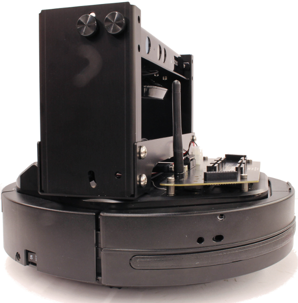
The Quanser QBot 2 is an Unmanned Ground Vehicle (UGV) built and sold by Quanser Inc. The QBot2 is based around a dual-core 1 GHz ARM Cortex-A9 processor with 1 GB RAM running Yocto Linux. The QUARC Target associated with the QBot2 is the QUARC Linux DuoVero Target. The QBot2 HIL card may only be used with QUARC when this target is selected. The following characteristics are of particular interest when using the QBot2 with QUARC:
**The serial port is accessed through the Stream API blocks, see Serial protocol.
***The SPI port is accessed through the Stream API blocks, see SPI protocol.
****The I2C port is accessed through the Stream API blocks, see I2C protocol.
The Quanser QBot 2 also supports specialized quantities such as the following:
The QUARC driver name for this card is qbot2.
To select the Quanser QBot 2 HIL board, select the QUARC qbot2 board type from the drop-down list on the Main tab of the HIL Initialize block.
| Note that the Linux DuoVero target must be selected to use the Quanser QBot 2 board. |
The Quanser QBot 2 I/O channels are described below.
Clocks
There are currently no configuration options for the Quanser QBot 2 clocks.
Analog Inputs
The Quanser QBot 2 supports 10 analog inputs. Hence, analog input channel numbers range from 0 to 9. The first four analog inputs are user accessible channels with a 0-5V range and 12-bit resolution. The full suite of analog inputs are enumerated in the table below:
|
Channel |
Description |
|---|---|
|
0-3 |
User-accessible analog inputs with 0-5V range and 12-bit resolution |
|
4 |
Battery voltage (typically 16.7V when fully charged) |
|
5 |
Raw voltage from right cliff sensor1 |
|
6 |
Raw voltage from central cliff sensor1 |
|
7 |
Raw voltage from left cliff sensor1 |
|
8 |
Right motor current in Amps. |
|
9 |
Left motor current in Amps. |
1 For the non-linear relationship between the raw voltage from a cliff sensor to actual distance, refer to the Sharp Analog Output Type Distance Measuring Sensor Data Sheet.
Analog Outputs
The Quanser QBot 2 card does not support analog outputs.
Digital Inputs
The Quanser QBot 2 supports 39 digital inputs. The first eight channels are user-accessible reconfigurable digital I/O lines that may be used as digital inputs. The full suite of digital inputs are enumerated in the following table:
|
Channel |
Description |
|---|---|
|
0-7 |
User-accessible bidirectional digital I/O lines |
|
8 |
Right bumper (0 = not pressed, 1 = pressed) |
|
9 |
Central bumper (0 = not pressed, 1 = pressed) |
|
10 |
Left bumper (0 = not pressed, 1 = pressed) |
|
11 |
Right wheel drop (0 = wheel up, 1 = wheel down) |
|
12 |
Left wheel drop (0 = wheel up, 1 = wheel down) |
|
13 |
Right cliff (0 = no cliff, 1 = cliff detected) |
|
14 |
Central cliff (0 = no cliff, 1 = cliff detected) |
|
15 |
Left cliff (0 = no cliff, 1 = cliff detected) |
|
16 |
Button B0 (0 = not pressed, 1 = pressed) |
|
17 |
Button B1 (0 = not pressed, 1 = pressed) |
|
18 |
Button B2 (0 = not pressed, 1 = pressed) |
|
19 |
Right motor overcurrent (0 = normal operation, 1 = overcurrent detected) |
|
20 |
Left motor overcurrent (0 = normal operation, 1 = overcurrent detected) |
|
21 |
Right dock IR near right sensor (0 = not detected, 1 = detected) |
|
22 |
Right dock IR near center sensor (0 = not detected, 1 = detected) |
|
23 |
Right dock IR near left sensor (0 = not detected, 1 = detected) |
|
24 |
Right dock IR far right sensor (0 = not detected, 1 = detected) |
|
25 |
Right dock IR far center sensor (0 = not detected, 1 = detected) |
|
26 |
Right dock IR far left sensor (0 = not detected, 1 = detected) |
|
27 |
Central dock IR near right sensor (0 = not detected, 1 = detected) |
|
28 |
Central dock IR near center sensor (0 = not detected, 1 = detected) |
|
29 |
Central dock IR near left sensor (0 = not detected, 1 = detected) |
|
30 |
Central dock IR far right sensor (0 = not detected, 1 = detected) |
|
31 |
Central dock IR far center sensor (0 = not detected, 1 = detected) |
|
32 |
Central dock IR far left sensor (0 = not detected, 1 = detected) |
|
33 |
Left dock IR near right sensor (0 = not detected, 1 = detected) |
|
34 |
Left dock IR near center sensor (0 = not detected, 1 = detected) |
|
35 |
Left dock IR near left sensor (0 = not detected, 1 = detected) |
|
36 |
Left dock IR far right sensor (0 = not detected, 1 = detected) |
|
37 |
Left dock IR far center sensor (0 = not detected, 1 = detected) |
|
38 |
Left dock IR far left sensor (0 = not detected, 1 = detected) |
Note that the dock IR signals may oscillate when the IR signal is detected. This oscillation is a function of the way the docking IR signals work.
Digital Outputs
The Quanser QBot 2 supports 17 digital outputs. The first eight channels are user-accessible reconfigurable digital I/O lines that may be used as digital outputs. The full suite of digital outputs are enumerated in the following table:
|
Channel |
Description |
|---|---|
|
0-7 |
User-accessible bidirectional digital I/O lines |
|
8 |
User LED (underneath board) |
|
9 |
Chassis LED1 red |
|
10 |
Chassis LED1 green |
|
11 |
Chassis LED2 red |
|
12 |
Chassis LED2 green |
|
13 |
Enable 3.3V power |
|
14 |
Enable 5V power |
|
15 |
Enable 12V/5A power1 |
|
16 |
Enable 12V/1.5A power |
1 Disabling the 12V/5A power will power down the Gumstix DuoVero processor. The chassis will have to be turned off and back on in order to restore power and wireless communications with the Gumstix DuoVero target.
Encoder Inputs
The Quanser QBot 2 supports four encoder inputs. The first two channels are user-accessible quadrature encoder inputs with 24-bit count values. These two channels support non-quadrature as well as full quadrature modes, along with the index pulse. The encoder channels are enumerated in the table below:
|
Channel |
Description |
|---|---|
|
0-1 |
User-accessible encoder inputs with 24-bit counters |
|
2 |
Right wheel |
|
3 |
Left wheel |
In order to set the encoder counters to a particular count or to change the default
quadrature when the model is loaded, the encoder inputs must
be configured on the HIL Initialize
block's Encoder Inputs tab. Set the Encoder input channels
field to all the encoder channels that will be
used on the board for the current diagram. For example, enter
0:1
to
indicate channels 0 through 1 are used as encoder inputs.
The Quanser QBot 2 supports non-quadrature (count and direction) and 4X quadrature modes for the first two encoder channels. The Quanser QBot 2 uses a filter frequency of 20 MHz which is not configurable.
The direction of the first two encoder channels may be reversed via the board-specific enc<n>_dir
options. The ability to reverse the direction in which the encoder counts is convenient when connecting
to hardware because it obviates the need for confusing sign changes in code.
The Quanser QBot 2 provides support for the index pulse on the first two encoder channels. The encoder count values when the last index pulses occurred are available as additional outputs. Refer to output input channels below for details.
The first two encoder counters may also be programmed to reload from the initial value when an index pulse
occurs. Set the appropriate enc<n>_reload flag in the board-specific options to enable
this feature. However, for control purposes, it is probably better to look for changes in the most recent
index position as reported by the other input channels than to have the actual encoder counts change
asynchronously with respect to the software.
The index pulse is detected when the A, B and Z signals of the encoder have a particular polarity. The polarity of each of these signals used to detect an index pulse is programmed through the board-specific options (see below). Doing so typically allows the index position to be determined with full quadrature accuracy. If the other input channels reflecting the position of the last index pulse continuously change as the encoder is rotated then the polarity of Z is likely incorrect.
The first two encoder inputs are sampled simultaneously when measured using a single HIL Read block.
Furthermore, the encoder positions and index positions are all sampled together simultaneously (in hardware) when measured using a single HIL Read block. This functionality is very useful for complex mechanical devices in which it is important to know the joint angles at a particular instant in time because small errors in these quantities could lead to inaccurate kinematic calculations. Without simultaneous sampling the mechanical system could not be guaranteed to be in exactly the same position when the different joint angles were measured.
PWM Outputs
The Quanser QBot 2 driver supports four generic user-accessible PWM output channels. Hence, PWM output channels range from 0 to 3.
In order to configure the PWM mode or frequency, or to set the value of the PWM outputs when the model is loaded or unloaded, the PWM
outputs must be configured on the HIL Initialize block's
PWM Outputs tab. Set the PWM output channels field to all the PWM output channels that will be used on the
board for the current diagram. For example, enter 0:1 to indicate channels 0 and 1. Specify 1 to indicate channel 1 alone.
The PWM output frequency (a.k.a., pulse rate) is suitable for a variety of applications, including driving additional R/C servos. To drive an R/C servo, set the PWM frequency to 50 Hz, which is equivalent to a PWM output period of 20 ms. Then drive a duty cycle between 0.05 and 0.10 to get a 1 ms to 2 ms pulse.
The initial and final PWM outputs may be set via the Initial PWM outputs and Final PWM outputs fields respectively.
For example, enter 0.075 to indicate a 7.5 % duty cycle. A 7.5% duty cycle (i.e., a 1.5-ms pulse width) typically corresponds to the neutral position for
R/C servos. If the vectors specified in these fields are shorter than the channel vector, the value of the last element in the vector will be used for the rest
of the channels. Hence, a scalar value will apply to all channels specified in the PWM output channels field.
Other Inputs
The Quanser QBot 2 supports ten other input channels. The other input channels are defined as follows:
|
Other Input Channel |
Description |
Units |
|---|---|---|
|
13000 |
Encoder 0 index position |
(counts) |
|
13001 |
Encoder 1 index position |
(counts) |
|
1002 |
Angle in Z-axis |
(rad) |
|
3000 |
Gyroscope in X |
(rad/s) |
|
3001 |
Gyroscope in Y |
(rad/s) |
|
3002 |
Gyroscope in Z |
(rad/s) |
|
11000 |
Right wheel PWM |
(%) |
|
11001 |
Left wheel PWM |
(%) |
|
12000 |
Timestamp |
(s) |
|
16000 |
Charger state |
1 |
1 The charger state takes on discrete values depending on whether the docking station is being used and whether the battery is fully charged. The following table shows the charger state values:
|
State |
Description |
|---|---|
|
0 |
Discharging battery |
|
2 |
Battery charged at docking station |
|
6 |
Battery charging at docking station |
|
18 |
Battery charged using adapter |
|
22 |
Battery charging using adapter |
Channel numbers for Other Input or Output channels use predefined ranges for each type of measurement to ensure consistency between data acquisition devices. Refer to QUARC Other Channels for a list of the Other Input or Output channel number ranges defined for any HIL Data Acquisition Card and their SI units.
Other Outputs
The Quanser QBot 2 supports four other output channels, allowing the wheel velocities to be controlled and sounds to be generated. Refer to the table below for a list of the channels:
|
Channel |
Description |
Units |
|---|---|---|
|
2000 |
Right wheel velocity |
(m/s) |
|
2001 |
Left wheel velocity |
(m/s) |
|
14000 |
Pitch of custom sound |
(Hz) |
|
16000 |
Predefined sound |
(0-6) |
Channel numbers for Other Input or Output channels use predefined ranges for each type of measurement to ensure consistency between data acquisition devices. Refer to QUARC Other Channels for a list of the Other Input or Output channel number ranges defined for any HIL Data Acquisition Card and their SI units.
Interrupts
The Quanser QBot 2 card, or its driver, does not support any interrupt sources.
Watchdog
The Quanser QBot 2 supports a watchdog timer for resetting the user-accessible outputs on watchdog expiry. Namely, the first nine digital output channels and the first four PWM channels will be reset to zero on watchdog expiry. Resetting of the outputs occurs without software intervention, and therefore may be used as a safety mechanism in the event of software failure.
To enable the watchdog, place a HIL Watchdog block in the diagram.
Once the watchdog has expired, further I/O on the user-accessible outputs is disabled until the watchdog state is cleared.
Use a HIL Watchdog Clear block to clear the watchdog state when the model is running. Restarting the model will also clear the watchdog state.
The watchdog timer may be programmed for any timeout period between 12.8 microseconds and 0.8389 seconds exclusive.
Board-Specific Options
pwm0_immediate
Set this option to "yes", "y" or "1" to update PWM outputs as soon as a value is written to PWM channel 0. Normally, the changes in the duty cycle of the PWM outputs are synchronized to the beginning of the PWM period to avoid glitches in the PWM outputs. Setting this option to "yes" causes the outputs to be updated immediately, even if it means producing a second pulse within the same PWM period. For example, when using trailing edge alignment, switching from a 90% duty cycle to a 10% duty cycle near the middle of the PWM period could cause the 90% duty cycle to be truncated immediately and then restarted near the end of the PWM period to generate the 10% duty cycle pulse. Some systems, however, do perform better when the PWM outputs are updated immediately, so this option is provided.
Similar options exist for the other PWM channels e.g. pwm1_immediate, pwm2_immediate, etc.
enc0_dir
Set this option to "yes", "y" or "1" to reverse the direction of encoder 0. This feature makes it easier to migrate to the Quanser QBot 2 hardware from another data acquisition card. It also allows models to be more portable to other cards.
Similar options exist for the other encoder channel i.e. enc1_dir.
enc0_filter
Set this option to "yes", "y" or "1" to enable filtering on encoder channel 0. The Quanser QBot 2 filtering oversamples the A, B and Z channels are tries to eliminate spurious glitches in the inputs. However, use of filtering slows down the maximum encoder velocity that may be measured.
Similar options exist for the other encoder channel i.e. enc1_filter.
enc0_a
This option determine the state of the A signal required for an index pulse to be recognized. Set this option to "yes", "y" or "1" to require that the A signal be high for an index pulse to be detected. Set it to "no", "n" or "0" to require the A signal to be low. If a Quanser QBot 2 terminal board is being used, then these polarities are reversed because the buffers on the terminal board are inverting. In that case, select "1" to require that A is low, and "0" to require that it be high.
Similar options exist for the other encoder channel i.e. enc1_a.
enc0_b
This option determine the state of the B signal required for an index pulse to be recognized. Set this option to "yes", "y" or "1" to require that the B signal be high for an index pulse to be detected. Set it to "no", "n" or "0" to require the B signal to be low. If a Quanser QBot 2 terminal board is being used, then these polarities are reversed because the buffers on the terminal board are inverting. In that case, select "1" to require that B is low, and "0" to require that it be high.
Similar options exist for the other encoder channel i.e. enc1_b.
enc0_z
This option determine the state of the Z signal required for an index pulse to be recognized. Set this option to "yes", "y" or "1" to require that the Z signal be high for an index pulse to be detected. Set it to "no", "n" or "0" to require the Z signal to be low. If a Quanser QBot 2 terminal board is being used, then these polarities are reversed because the buffers on the terminal board are inverting. In that case, select "1" to require that Z is low, and "0" to require that it be high.
Similar options exist for the other encoder channel i.e. enc1_z.
 If this option is set incorrectly then an index pulse is detected every time the A and B signals match the criteria defined
by the enc0_a and enc0_b options - which is basically "all" the time. If the index
position vary seemingly continuously, try changing this option to the opposite polarity.
If this option is set incorrectly then an index pulse is detected every time the A and B signals match the criteria defined
by the enc0_a and enc0_b options - which is basically "all" the time. If the index
position vary seemingly continuously, try changing this option to the opposite polarity.
enc0_reload
Set this option to "yes", "y" or "1" to reload encoder counter 0 when the index pulse occurs. This option is generally not recommended because it wreaks havoc on controllers if the controller is not carefully designed. The Quanser QBot 2 keeps track of the last position at which an index pulse occurred in a separate set of registers, so reloading the encoder counter on an index pulse is less important.
Similar options exist for the other encoder channel i.e. enc1_reload.
Properties
The Quanser QBot 2 driver currently supports the following read-only properties:
|
Property |
Type |
Description |
|---|---|---|
|
PROPERTY_INTEGER_MAJOR_VERSION |
Integer |
Major version number of the hardware |
|
PROPERTY_INTEGER_MINOR_VERSION |
Integer |
Minor version number of the hardware |
|
PROPERTY_INTEGER_BUILD |
Integer |
Build number of the hardware (currently always zero) |
|
PROPERTY_INTEGER_REVISION |
Integer |
Revision or patch number of the hardware |
|
PROPERTY_INTEGER_FIRMWARE_MAJOR_VERSION |
Integer |
Major version number of the firmware |
|
PROPERTY_INTEGER_FIRMWARE_MINOR_VERSION |
Integer |
Minor version number of the firmware |
|
PROPERTY_INTEGER_FIRMWARE_BUILD |
Integer |
Build number of the firmware (currently always zero) |
|
PROPERTY_INTEGER_HARDWARE_VERSION |
Integer |
Revision or patch number of the firmware |
|
PROPERTY_INTEGER_KOBUKI_UDID0 |
Integer |
Unique identifier 0 |
|
PROPERTY_INTEGER_KOBUKI_UDID1 |
Integer |
Unique identifier 1 |
|
PROPERTY_INTEGER_KOBUKI_UDID2 |
Integer |
Unique identifier 2 |
The following properties may be both read and written:
|
Property |
Type |
Description |
|---|---|---|
|
PROPERTY_DOUBLE_KOBUKI_P_GAIN |
Double |
Proportional gain for the onboard controller. The factory value is 100. |
|
PROPERTY_DOUBLE_KOBUKI_I_GAIN |
Double |
Integral gain for the onboard controller. The factory value is 0.1. |
|
PROPERTY_DOUBLE_KOBUKI_D_GAIN |
Double |
Derivative gain for the onboard controller. The factory value is 2. |
Targets
|
Target |
Supported |
Comments |
|---|---|---|
|
No |
Not supported. |
|
|
No |
Not supported. |
|
|
No |
Not supported. |
|
|
No |
Not supported. |
|
|
No |
Not supported. |
|
|
No |
Not supported. |
|
|
No |
Not supported. |
|
|
No |
Not supported. |
|
|
No |
Not supported. |
|
|
No |
Not supported. |
|
|
No |
Not supported. |
|
|
Yes |
Only supported with a QBot 2 device. |
|
|
No |
Not supported. |
|
|
No |
Not supported. |
|
|
No |
Not supported. |
|
|
Rapid Simulation (RSIM) Target |
Yes |
Supported with no communication to the hardware. |
|
Normal simulation |
Yes |
Supported with no communication to the hardware. |
See Also
Copyright ©2026 Quanser Inc. This page was generated 2026-05-13. Submit feedback to Quanser about this page.
Link to this page.