
Quanser QBot Platform
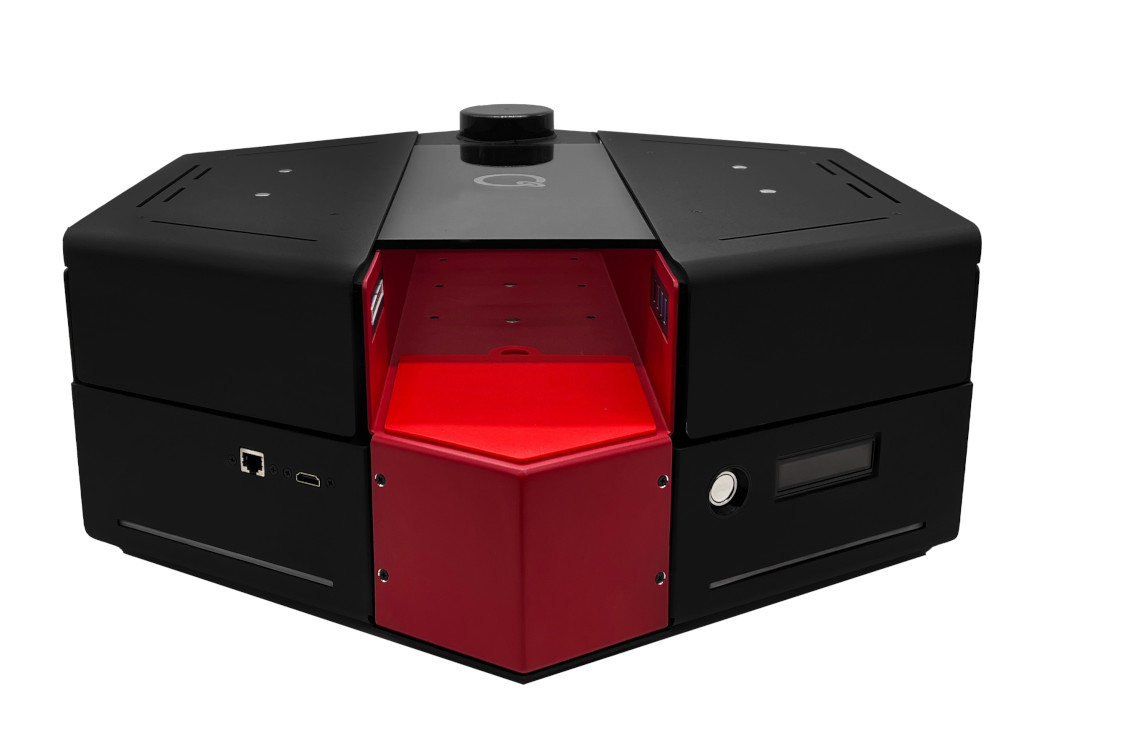
The Quanser QBot Platform is an Unmanned Ground Vehicle (UGV) built and sold by Quanser Inc. The Quanser QBot Platform is based around an NVIDIA Jetson Orin Nano, which has a 6-core Arm® Cortex®-A78AE v8.2, 1.7 GHz 64-bit CPU with 8 GB 64-bit LPDDR5 34 GB/s RAM. It also contains a 1024-core NVIDIA Ampere GPU with 32 Tensor cores with CUDA support, an Intel D435 RGBD camera and additional I/O supplied by Quanser. The latest operating system installed on the Quanser QBot Platform is a customized version of Linux for Tegra from JetPack 5.1.3. The QUARC Target associated with the Quanser QBot Platform is the QUARC Linux QBot Platform Target. The Quanser QBot Platform HIL card may only be used with QUARC when this target is selected. The following characteristics are of particular interest when using the Quanser QBot Platform with QUARC:
* Communications channels are accessed through the Stream API blocks, see Serial protocol,
SPI protocol and I2C protocol.
The QUARC driver name for this card is qbot_platform.
To select the Quanser QBot Platform HIL board, select the QUARC qbot_platform board type from the drop-down list on the Main tab of the HIL Initialize block.
| Note that the QUARC Linux QBot Platform Target must be selected to use the Quanser QBot Platform board. |
The Quanser QBot Platform supports different means of communicating with it as a target. It supports wireless (WiFi) communications, which is most readily configured initially by connecting a monitor, mouse and keyboard and using the Ubuntu OS desktop to connect to the WiFi router. If a wireless connection is used then its IP address will show up on the LCD display with a WiFi symbol beside it. Once configured, it should reconnect automatically whenever the WiFi signal is available.s
The Quanser QBot Platform also supports a 10/100/1000 Mbps wired LAN connection. If the LAN connection is used, its IP address will show up on the LCD display with a LAN symbol beside it. If both WiFi and LAN are connected then the LAN IP address will be displayed on the LCD display, as it is the fastest connection. In the case of WiFi or LAN the IP address is determined by the adapter settings. Typically, the IP address is assigned dynamically by a DHCP server on the network.
Display
The LCD display on the Quanser QBot Platform typically displays the battery voltage and IP address of the card, as well as status messages.
The LCD display on the Quanser QBot Platform may also be driven from QUARC using the LCD Display block.
Select the WS0010 display type.
The URI to use for this display is lcd://qbot_platform:1.
|
The LCD has a refresh rate of 49 Hz, thus it would not show the display characters if the LCD is being written faster than that. In certain conditions,
if the LCD is not able to keep up, a message |
Communications
The communications ports provided on the Quanser QBot Platform board can be utilized through the QUARC Communications blockset and the Quanser Stream API (see QUARC Communications Protocols).
For SPI communications, a sample URI for communications would be:
spi://localhost:0?baud='10000000',phase='off',lsb='off',frame='0'
where the frame option selects the SPI CS line to frame the SPI bus transaction (0 or 1). Note that the SPI port must be enabled using the jetson-io.py utility for SPI communications to be used. Once the SPI port is enabled, the corresponding digital I/O will no longer be available as digital I/O.
| In the jetson-io.py utility, SPI 0 is labelled as "spi1", and SPI 3 is labelled as "spi3". This confusion is due to internal naming on the Jetson that does not match the Linux kernel numbering. Also, the minimum baud rate for the SPI clock is 3.1875 Mz, while the maximum rate is 24 MHz. |
For I2C communications, a sample URI for communications would be:
i2c://localhost:0?baud='400000',address=0x69
where the address option specifies the I2C slave address. Note that the I2C port must be enabled using the jetson-io.py utility for I2C communications to be used. Once the I2C port is enabled, the corresponding digital I/O will no longer be available as digital I/O.
| In the jetson-io.py utility, I2C 1 is labelled as "i2c2", and I2C 7 is labelled as "i2c8". This confusion is due to internal naming on the Jetson that does not match the Linux kernel numbering. |
For serial communications, a sample URI for communications would be:
serial://localhost:1?baud='115200',word='8',parity='none',stop='1'
The UART must be enabled using the jetson-io.py utility for UART communications to be used. Once the UART port is enabled, the corresponding digital I/O will no longer be available as digital I/O.
| In the jetson-io.py utility, UART 1 is labelled as "uarta". This confusion is due to internal naming on the Jetson that does not match the Linux kernel numbering. Also, the minimum baud rate is 778 Hz, while the maximum baud rate is 4.25 MHz. |
Clocks
There are currently no configuration options for the Quanser QBot Platform clocks.
To use the extperiph3 and extperiph4 clocks on the 40-pin expansion connector, first enable the desired clock
using the
jetson-io.py
tool in the /opt/nvidia/jetson-io folder. The
jetson-io.py
utility must be run with root privileges.
Then log on to the QBot Platform and enter a root shell using the command:
sudo su
Change to the /sys/kernel/debug/bpmp/debug/clk/extperiph3 or /sys/kernel/debug/bpmp/debug/clk/extperiph4 folder
as appropriate for the desired clock:
cd /sys/kernel/debug/bpmp/debug/clk/extperiph3
To see the range of clock rates permissible, print the values of the min_rate and max_rate files:
    cat min_rate
    cat max_rate
To enable the clock and set the current clock frequency in Hz, use the following commands. This example assumes a 1 MHz clock frequency is desired:
    echo 1 > mrq_rate_locked
    echo 1 > state
    echo 1000000 > rate
To disable the clock, reverse the operations used to enable the clock:
    echo 0 > state
    echo 0 > mrq_rate_locked
Analog Inputs
The Quanser QBot Platform supports 6 analog inputs. Hence, analog input channel numbers range from 0 to 5. The full suite of analog inputs are enumerated in the table below:
|
Channel |
Description |
|---|---|
|
0 |
Battery 0 voltage (typically 12.1V when fully charged) |
|
1 |
Battery 1 voltage (typically 12.1V when fully charged) |
|
2 |
Motor 0 (left) current in Amps |
|
3 |
Motor 1 (right) current in Amps |
|
4 |
PCB current in Amps |
|
5 |
PCB voltage |
Analog Outputs
The Quanser QBot Platform card does not support analog outputs.
Digital Inputs
The Quanser QBot Platform supports 40 digital inputs. The first 28 channels are user-accessible reconfigurable digital I/O lines that may be used as digital inputs. Channels 0 and 1, however, are reserved for a HAT EEPROM I2C interface. A digital I/O line cannot be used as an input and output at the same time. Nor can it be used for communications (SPI, I2C or UART) or PWM at the same time.
Since the digital I/O lines may be individually programmed as inputs or
outputs on the Quanser QBot Platform, all channels which will be used for digital inputs
should be configured on the HIL Initialize
block's Digital Inputs tab. Set the Digital input channels field to all
the digital I/O channels that will be used as digital inputs on the board for the current diagram. For example, enter
2:4 to designate channels 2 through 4 as digital inputs. Specify
[2, 4, 5] to indicate that channels 2, 4 and 5 are to be configured
as digital inputs.
| Note that digital lines 14 and 17 are unidirectional outputs and cannot be configured as digital inputs. |
The full suite of digital inputs are enumerated in the following table:
|
Channel |
Description |
|---|---|
|
0-27 |
User-accessible bidirectional digital I/O lines, except lines 14 and 17 which are always outputs. |
|
28 |
Motor 0 (left) stall detect |
|
29 |
Motor 0 (left) stall error |
|
30 |
Motor 0 (left) overcurrent detect |
|
31 |
Motor 0 (left) overcurrent error |
|
32 |
Motor 1 (right) stall detect |
|
33 |
Motor 1 (right) stall error |
|
34 |
Motor 1 (right) overcurrent detect |
|
35 |
Motor 1 (right) overcurrent error |
|
36 |
Limit switch 0 |
|
37 |
Limit switch 1 |
|
38 |
Battery 0 connected |
|
39 |
Battery 1 connected |
Digital Outputs
The Quanser QBot Platform supports 32 digital outputs. The first 28 channels are user-accessible reconfigurable digital I/O lines that may be used as digital outputs. A digital I/O line cannot be used as an input and output at the same time. Nor can it be used for communications (SPI, I2C or UART) or PWM at the same time.
Since the digital I/O lines may be individually programmed as inputs or outputs
on the Quanser QBot Platform, all the channels which will be used for digital outputs should be configured
on the HIL Initialize block's
Digital Outputs tab. Set the Digital output channels
field to all the bidirectional digital I/O channels that will
be used as digital outputs on the board for the current diagram. For example, enter
2:4 to designate channels 2 through 4 as digital outputs. Specify
[2, 4, 5] to indicate that channels 2, 4 and 5 are to be configured
as digital outputs.
To set the digital output values when the model is loaded or unloaded, set the Initial digital outputs and Final digital outputs to the desired values respectively. If the vectors specified in these fields are shorter than the channel vector, the value of the last element in the vector will be used for the rest of the channels. Hence, a scalar value will apply to all channels specified in the Digital output channels field.
| Note that digital lines 15 and 16 are unidirectional inputs and cannot be configured as digital outputs. |
The full suite of digital outputs are enumerated in the following table:
|
Channel |
Description |
|---|---|
|
0-27 |
User-accessible bidirectional digital I/O lines, except lines 15 and 16 which are always inputs. |
|
28 |
Motor 0 (left) enable |
|
29 |
Motor 1 (right) enable |
|
30 |
QArm mini power enable |
|
31 |
Doward facing LEDs power enable |
Encoder Inputs
The Quanser QBot Platform supports two encoder inputs. The encoder channels are enumerated in the table below:
|
Channel |
Description |
|---|---|
|
0 |
Motor 0 (left) |
|
1 |
Motor 1 (right) |
In order to set the encoder counters to a particular count, the encoder inputs must
be configured on the HIL Initialize
block's Encoder Inputs tab. Set the Encoder input channels
field to all the encoder channels that will be
used on the board for the current diagram. For example, enter
0:1
to
indicate channels 0 through 1 are used as encoder inputs.
PWM Outputs
The Quanser QBot Platform driver supports up to 5 PWM output channels. Hence, PWM output channels range from 0 to 4. Each PWM channel is completely independent and can have its own duty cycle and frequency.
Channels 0 and 1 are used to control the two motors on the Quanser QBot Platform, with fixed mode (duty cycle), frequency (23195), configuration (bipolar), alignment (leading-edge), and polarity (active high) settings.
Channels 2 to 4 are the Orin Nano GPIO PWM channels, which can have frequencies between 1.52 Hz and 1592356 Hz. Before they may be used, they must be configured using the jetson-io.py utility. The jetson-io.py utility must be run with root privileges. The following table documents the PWM channel, GPIO number, and jetson-io.py utility name for each PWM channel for the Orin Nano GPIO PWM channel.
|
PWM channel |
GPIO number |
jetson-io name |
|---|---|---|
|
2 |
GPIO 22 |
pwm1 |
|
3 |
GPIO 13 |
pwm5 |
|
4 |
GPIO 12 |
pwm7 |
| Note that once a GPIO is configured as a PWM channel then it will no longer be recognized as a digital I/O line. |
In order to configure the PWM mode or frequency, or to set the value of the PWM outputs when the model is loaded or unloaded, the PWM
outputs must be configured on the HIL Initialize block's
PWM Outputs tab. Set the PWM output channels field to all the PWM output channels that will be used on the
board for the current diagram. For example, enter 0:1 to indicate channels 0 and 1. Specify 1 to indicate channel 1 alone.
The maximum frequency for theses generic PWM channel is 800 kHz, and the minimum frequency is 9.1553 Hz.
Set the PWM output frequency (a.k.a., pulse rate) in the "Frequencies in Hz or duty cycle" field. The PWM output mode is typically set to duty cycle mode (0) or time mode (4) when driving ESCs or R/C servos. Set the Initial PWM outputs and Final PWM outputs fields to the desired initial and final output values respectively. The interpretation of these output values depends on the PWM mode selected. If the vectors specified in these fields are shorter than the channel vector, the value of the last element in the vector will be used for the rest of the channels. Hence, a scalar value will apply to all channels specified in the PWM output channels field.
Other Inputs
The Quanser QBot Platform supports eight other input channels. The other input channels are defined as follows:
|
Other Input Channel |
Description |
Units |
|---|---|---|
|
3000 |
Gyroscope in X |
(rad/s) |
|
3001 |
Gyroscope in Y |
(rad/s) |
|
3002 |
Gyroscope in Z |
(rad/s) |
|
3003 |
Motor 0 (left) speed |
(rad/s) |
|
3004 |
Motor 1 (right) speed |
(rad/s) |
|
4000 |
Accelerometer in X |
(m/s2) |
|
4001 |
Accelerometer in Y |
(m/s2) |
|
4002 |
Accelerometer in Z |
(m/s2) |
|
14000 |
Encoder velocity for motor 0 (left) |
(counts/s) |
|
14001 |
Encoder velocity for motor 1 (right) |
(counts/s) |
Channel numbers for Other Input or Output channels use predefined ranges for each type of measurement to ensure consistency between data acquisition devices. Refer to QUARC Other Channels for a list of the Other Input or Output channel number ranges defined for any HIL Data Acquisition Card and their SI units.
Other Outputs
The Quanser QBot Platform supports six other output channels. Refer to the table below for a list of the channels:
|
Channel |
Description |
Units |
|---|---|---|
|
11000 |
LED strip 0 red |
(0.0 to 1.0 represending 0% to 100%) |
|
11001 |
LED strip 0 green |
(0.0 to 1.0 represending 0% to 100%) |
|
11002 |
LED strip 0 blue |
(0.0 to 1.0 represending 0% to 100%) |
|
11003 |
LED strip 1 red |
(0.0 to 1.0 represending 0% to 100%) |
|
11004 |
LED strip 1 green |
(0.0 to 1.0 represending 0% to 100%) |
|
11005 |
LED strip 1 blue |
(0.0 to 1.0 represending 0% to 100%) |
|
3000 |
Motor 0 (left) speed command |
(rad/s) |
|
3001 |
Motor 1 (right) speed command |
(rad/s) |
Channel numbers for Other Input or Output channels use predefined ranges for each type of measurement to ensure consistency between data acquisition devices. Refer to QUARC Other Channels for a list of the Other Input or Output channel number ranges defined for any HIL Data Acquisition Card and their SI units.
Interrupts
The Quanser QBot Platform card, or its driver, does not support any interrupt sources.
Watchdog
The Quanser QBot Platform supports a watchdog timer for resetting outputs on watchdog expiry. The board will reset digital outputs 28-30, PWM outputs 0-1, and other outputs to the user-configured values when the watchdog expires. Resetting of the outputs occurs without software intervention, and therefore may be used as a safety mechanism in the event of software failure.
Place a HIL Watchdog block in the diagram to program the watchdog timer. This block also reloads the watchdog each time it is executed.
Once the watchdog has expired, further I/O is disabled until the watchdog state is cleared.
Hence, in Simulink models, the outputs will remain reset after watchdog expiration even after the model is stopped, unless a HIL Watchdog Clear block is used to clear the watchdog state. Restarting the model also causes the watchdog state to be cleared, allowing the outputs to be used once more. These semantics make the watchdog useful for ensuring product safety.
 Due to safety reason, the Quanser QBot Platform has a 3 seconds watchdog automatically configured and enabled. This ensures that in
the event of software crashes, the motors on Quanser QBot Platform would be safely shutdown.
Due to safety reason, the Quanser QBot Platform has a 3 seconds watchdog automatically configured and enabled. This ensures that in
the event of software crashes, the motors on Quanser QBot Platform would be safely shutdown.
Board-Specific Options
The Quanser QBot Platform has a number of board-specific options to control specialized functionality of the board. These options configure the IMU and PWM.
motor_mode
This option configures the operating mode of the two motors. The valid values are:
|
Operating Mode |
Value |
|---|---|
|
PWM Mode |
0 |
|
Velocity Mode |
1 |
pwm_limit
Set this option to the minimum PWM command that can be applied to the motors. This limit applies to all motor_mode. The maximum value is 0.7.
motor0_deadband_compensation
This option offsets the motor 0 (left) command by the specified PWM command (i.e. range of 0 to 1) to compensate for amplifier deadband.
motor1_deadband_compensation
This option offsets the motor 1 (right) command by the specified PWM command (i.e. range of 0 to 1) to compensate for amplifier deadband.
enc0_velocity
Set this option to the minimum velocity in counts per second that should be detected by the motor digital tachometer. This limit
is an artificial limit that is useful when friction stops the device long before it reaches the slowest detectable velocity of
the Quanser QBot Platform hardware. If this option is set to zero then the slowest velocity measurable by the hardware is used. The default
value is enc0_velocity=0.0 which disables the clamping function.
enc1_velocity
Set this option to the minimum velocity in counts per second that should be detected by the pendulum digital tachometer. This limit
is an artificial limit that is useful when friction stops the device long before it reaches the slowest detectable velocity of
the Quanser QBot Platform hardware. If this option is set to zero then the slowest velocity measurable by the hardware is used. The default
value is enc1_velocity=0.0 which disables the clamping function.
gyro_rate
This option sets gyroscope's sensor's sampling rate. Valid values range from 12.5 to 32000. The units are Hz.
gyro_ord
This option determines the order of the filter used for gyroscope's onboard filtering. Valid values are 1, 2 or 3.
gyro_fs
This option sets the full-scale range of gyroscope's sensor. Valid values range from 15.625 to 2000. The units are degrees per second.
gyro_bw
This option sets the bandwidth of the filter used for gyroscope's onboard filtering. Valid values range from 10 to 16000. The units are Hertz.
accel_rate
This option sets accelerometer's sampling rate. Valid values range from 12.5 to 32000. The units are Hz.
accel_ord
This option sets the order of the filter used for accelerometer's onboard filtering. Valid values are 1, 2 or 3.
accel_fs
This option configures the full-scale range of accelerometer. Valid values are 2 to 16. The units are g's.
accel_bw
This option sets the bandwidth of the filter used for acceleromter's onboard filtering. Valid values range from 10 to 16000. The units are Hz.
Properties
The Quanser QBot Platform driver currently supports a number of double properties used to tune the internal Speed Controller gains for the motors. The double properties are enumerated in the table below:
|
Property |
Type |
Description |
|---|---|---|
|
PROPERTY_DOUBLE_QBOT_PLATFORM_P_GAIN |
Double |
Proportional Gain |
|
PROPERTY_DOUBLE_QBOT_PLATFORM_I_GAIN |
Double |
Integral Gain |
|
PROPERTY_DOUBLE_QBOT_PLATFORM_FF |
Double |
Feedforward Term |
The Quanser QBot Platform driver also supports the following read-only properties:
|
Property |
Type |
Description |
|---|---|---|
|
PROPERTY_INTEGER_FIRMWARE_MAJOR_VERSION |
Integer |
Major version number of the firmware |
|
PROPERTY_INTEGER_FIRMWARE_MINOR_VERSION |
Integer |
Minor version number of the firmware |
|
PROPERTY_INTEGER_FIRMWARE_BUILD |
Integer |
Build number of the firmware (currently always zero) |
|
PROPERTY_INTEGER_HARDWARE_VERSION |
Integer |
Revision or patch number of the firmware |
Connectors
The Quanser QBot Platform board has one connector for expansion I/O. The pinouts for this connector are listed below. Note that all pins are 3.3V and are not 5V tolerant unless marked otherwise. Exceeding these voltages may damage the board!
Qbot Platform GPIO Connector
I2S 2 SDOUT ← / GPIO 21 ↔ | 40 | 39 | ― Ground |
I2S 2 SDIN ← / GPIO 20 ↔ | 38 | 37 | ↔ GPIO 26 / → SPI 1 MOSI |
UART 1 CTS → / GPIO 16 (in) → | 36 | 35 | ↔ GPIO 19 / → I2S 2 LRCK |
Ground ― | 34 | 33 | ↔ GPIO 13 / → PWM 5 |
PWM 7 ← / GPIO 12 ↔ | 32 | 31 | ↔ GPIO 6 / → EXT PERIPH CLK 4 |
Ground ― | 30 | 29 | ↔ GPIO 5 / → EXT PERIPH CLK 3 |
I2C 1 SCL ↔ / GPIO 1 ↔ | 28 | 27 | ↔ GPIO 0 / ↔ I2C 1 SDA |
SPI 0 CS1 ← / GPIO 7 ↔ | 26 | 25 | ― Ground |
SPI 0 CS0 ← / GPIO 8 ↔ | 24 | 23 | ↔ GPIO 11 / → SPI 0 SCK |
SPI 1 MISO ← / GPIO 25 ↔ | 22 | 21 | ↔ GPIO 9 / ← SPI 0 MISO |
Ground ― | 20 | 19 | ↔ GPIO 10 / → SPI 0 MOSI |
SPI 1 CS0 ← / GPIO 24 ↔ | 18 | 17 | ― 3.3V |
SPI 1 CS1 ← / GPIO 23 ↔ | 16 | 15 | ↔ GPIO 22 / → PWM 1 |
Ground ― | 14 | 13 | ↔ GPIO 27 / → SPI 1 SCK |
I2S 2 SCLK ← / GPIO 18 ↔ | 12 | 11 | → GPIO 17 (out) / → UART 1 RTS |
UART 1 RXD → / GPIO 15 (in) → | 10 | 9 | ― Ground |
UART 1 TXD ← / GPIO 14 (out) ← | 8 | 7 | ↔ GPIO 4 / ↔ AUD |
Ground ― | 6 | 5 | ↔ GPIO 3 / I2C 7 SCL |
5V ― | 4 | 3 | ↔ GPIO 2 / I2C 7 SDA |
5V ― | 2 | 1 | ― 3.3V |
Legend
→▯← | = | input |
←▯→ | = | output |
↔▯↔ | = | bidirectional I/O |
= | 3.3V signal | |
= | power | |
= | ground |
Software
The following table lists particularly relevant software that has been installed and its associated version, in the event that the software gets upgraded accidentally and it is necessary to recover working versions. If a version is highlighted in red then it is highly recommended that it not be updated as it is likely optimized specifically for the target platform.
Package |
Type |
Version |
Description |
|---|---|---|---|
|
bc |
debian |
1.07.1-2build1 |
GNU bc arbitrary precision calculator language |
|
build-essential |
debian |
12.8ubuntu1.1 |
Tools essential for building C and C++ code, including the compilers, make and other development tools. |
|
cffi |
python |
1.16.0 |
Foreign Function Interface for Python calling C code. |
|
clang |
debian |
1:10.0-50~exp1 |
C, C++ and Objective-C compiler (LLVM based) |
|
curl |
debian |
7.68.0-1ubuntu2.22 |
command line tool for transferring data with URL syntax |
|
Cython |
python |
3.0.10 |
The Cython compiler for writing C extensions in the Python language. |
|
docker-buildx-plugin |
debian |
0.14.1-1~ubuntu.20.04~focal |
Docker Buildx cli plugin. |
|
future |
python |
0.18.2 |
Clean single-source support for Python 3 and 2 |
|
g++ |
debian |
4:9.3.0-1ubuntu2 |
GNU C++ compiler |
|
gcc |
debian |
4:9.3.0-1ubuntu2 |
GNU C compiler |
|
gettext-base |
debian |
0.19.8.1-10build1 |
GNU Internationalization utilities for the base system |
|
gfortran |
debian |
4:9.3.0-1ubuntu2 |
GNU Fortran 95 compiler |
|
gnupg2 |
debian |
2.2.19-3ubuntu2.2 |
GNU privacy guard - a free PGP replacement (dummy transitional package) |
|
h5py |
python |
3.6.0 |
Read and write HDF5 files from Python |
|
hdf5-tools |
debian |
1.10.4+repack-11ubuntu1 |
Hierarchical Data Format 5 (HDF5) - Runtime tools |
|
iputils-ping |
debian |
3:20190709-3ubuntu1 |
Tools to test the reachability of network hosts |
|
Keras-Preprocessing |
python |
1.1.2 |
Easy data preprocessing and data augmentation for deep learning models |
|
libblas-dev |
debian |
3.9.0-1build1 |
Basic Linear Algebra Subroutines 3, static library |
|
libbz2-dev |
debian |
1.0.8-2 |
high-quality block-sorting file compressor library - development |
|
libc++-dev |
debian |
1:10.0-50~exp1 |
LLVM C++ Standard library (development files) |
|
libcanberra-gtk-module |
debian |
0.30-7ubuntu1 |
translates GTK+ widgets signals to event sounds |
|
libcgal-dev |
debian |
5.0.2-3 |
C++ library for computational geometry (development files) |
|
libffi-dev |
debian |
3.3-4 |
Foreign Function Interface library (development files) |
|
libfreenect0.5 |
debian |
1:0.5.3-2 |
library for accessing Kinect device |
|
libfreetype6-dev |
debian |
2.10.1-2ubuntu0.3 |
FreeType 2 font engine, development files (transitional package) |
|
libgtk-3-0 |
debian |
3.24.20-0ubuntu1.1 |
GTK graphical user interface library |
|
libhdf5-dev |
debian |
1.10.4+repack-11ubuntu1 |
Hierarchical Data Format 5 (HDF5) - development files - serial version |
|
libjpeg8-dev |
debian |
8c-2ubuntu8 |
Independent JPEG Group's JPEG runtime library (dependency package) |
|
liblapack-dev |
debian |
3.9.0-1build1 |
Library of linear algebra routines 3 - static version |
|
liblzma-dev |
debian |
5.2.4-1ubuntu1.1 |
XZ-format compression library - development files |
|
libncurses5-dev |
debian |
6.2-0ubuntu2.1 |
transitional package for libncurses-dev |
|
libopenblas-dev |
debian |
0.3.8+ds-1ubuntu0.20.04.1 |
Optimized BLAS (linear algebra) library (dev, meta) |
|
libpng-dev |
debian |
1.6.37-2 |
PNG library - development (version 1.6) |
|
libreadline-dev |
debian |
8.0-4 |
GNU readline and history libraries, development files |
|
librealsense2 |
debian |
2.49.0 |
librealsense2 built using CMake |
|
libsqlite3-dev |
debian |
3.31.1-4ubuntu0.6 |
SQLite 3 development files |
|
libssl-dev |
debian |
1.1.1f-1ubuntu2.22 |
Secure Sockets Layer toolkit - development files |
|
libxml2-dev |
debian |
2.9.10+dfsg-5ubuntu0.20.04.7 |
Development files for the GNOME XML library |
|
libxslt1-dev |
debian |
1.1.34-4ubuntu0.20.04.1 |
XSLT 1.0 processing library - development kit |
|
lld-9 |
debian |
1:9.0.1-12 |
LLVM-based linker |
|
locales |
debian |
2.31-0ubuntu9.16 |
GNU C Library: National Language (locale) data [support] |
|
mock |
python |
3.0.5 |
Rolling backport of unittest.mock for all Pythons |
|
moreutils |
debian |
0.63-1 |
additional Unix utilities |
|
numpy |
python |
1.22.0 |
NumPy is the fundamental package for array computing with Python. |
|
nvidia-jetpack |
debian |
5.1.3-b29 |
NVIDIA Jetpack Meta Package |
|
onnx |
python |
1.16.1 |
Open Neural Network Exchange |
|
opencv-python |
python |
4.9.0.80 |
Wrapper package for OpenCV python bindings. |
|
openssl |
debian |
1.1.1f-1ubuntu2.22 |
Secure Sockets Layer toolkit - cryptographic utility |
|
packaging |
python |
24.0 |
Core utilities for Python packages |
|
pkgconfig |
python |
1.5.5 |
Interface Python with pkg-config |
|
protobuf |
python |
4.25.3 |
Protocol Buffers - Google's data interchange format. |
|
pybind11 |
python |
2.12.0 |
Seamless operability between C++11 and Python |
|
pygame |
python |
2.5.2 |
Python Game Development |
|
pyqtgraph |
python |
0.13.3 |
Scientific Graphics and GUI Library for Python |
|
pyquaternion |
python |
0.9.9 |
A fully featured, pythonic library for representing and using quaternions. |
|
python-openssl |
debian |
19.0.0-1build1 |
Python 2 wrapper around the OpenSSL library |
|
python3-colcon-common-extensions |
debian |
0.3.0-1 |
Meta package aggregating colcon-core and common extensions. |
|
python3-matplotlib |
debian |
3.1.2-1ubuntu4 |
Python based plotting system in a style similar to Matlab (Python 3) |
|
python3-pip |
debian |
20.0.2-5ubuntu1.10 |
Python package installer |
|
python3-rosdep |
debian |
0.24.0-1 |
rosdep package manager abstraction tool for ROS |
|
python3-rosinstall |
debian |
0.7.8-4 |
Installer for Robot OS (Python 3) |
|
python3-rosinstall-generator |
debian |
0.1.23-1 |
A tool for generating rosinstall files |
|
python3-sklearn |
debian |
0.22.2.post1+dfsg-5 |
Python modules for machine learning and data mining - Python 3 |
|
python3-wstool |
debian |
0.1.18-2 |
Commands to manage multi-VCS repositories (for Robot OS) Python 3 |
|
ros-dev-tools |
debian |
1.0.1 |
Developer Tools for ROS |
|
ros-galactic-ros1-bridge |
debian |
0.10.1-2focal.20221208.082233 |
A simple bridge between ROS 1 and ROS 2 |
|
ros-humble-cartographer-rviz |
debian |
2.0.9000-2focal.20231230.121619 |
Cartographer is a system that provides real-time simultaneous localization and mapping (SLAM) in 2D and 3D across multiple platforms and sensor configurations. |
|
ros-humble-desktop |
debian |
0.10.0-1focal.20231230.132335 |
A package which extends 'ros_base' and includes high level packages like vizualization tools and demos. |
|
ros-humble-rtabmap-ros |
debian |
0.21.1-1focal.20231230.122458 |
RTAB-Map Stack |
|
ros-humble-vision-opencv |
debian |
3.2.1-1focal.20231229.234150 |
Packages for interfacing ROS2 with OpenCV, a library of programming functions for real time computer vision. |
|
ros-noetic-desktop-full |
debian |
1.5.0-1focal.20240522.190153 |
A metapackage to aggregate several packages. |
|
ros-noetic-hector-slam |
debian |
0.5.2-4focal.20240521.164136 |
The hector_slam metapackage that installs hector_mapping and related packages. |
|
rsync |
debian |
3.1.3-8ubuntu0.7 |
fast, versatile, remote (and local) file-copying tool |
|
scons |
debian |
3.1.2-2 |
replacement for make |
|
setuptools |
python |
65.5.0 |
Easily download, build, install, upgrade, and uninstall Python packages |
|
six |
python |
1.16.0 |
Python 2 and 3 compatibility utilities |
|
tensorflow |
python |
2.12.0+nv23.6 |
TensorFlow is an open source machine learning framework for everyone. |
|
testresources |
python |
2.0.1 |
Testresources, a pyunit extension for managing expensive test resources |
|
torch |
python |
2.1.0a0+41361538.nv23.6 |
Tensors and Dynamic neural networks in Python with strong GPU acceleration |
|
torchvision |
python |
0.16.2+c6f3977 |
image and video datasets and models for torch deep learning |
|
v4l-utils |
debian |
1.18.0-2build1 |
Collection of command line video4linux utilities |
|
xrdp |
debian |
0.9.12-1ubuntu0.1 |
Remote Desktop Protocol (RDP) server |
|
zip |
debian |
3.0-11build1 |
Archiver for .zip files |
|
zlib1g-dev |
debian |
1:1.2.11.dfsg-2ubuntu1.5 |
compression library - development |
Targets
|
Target |
Supported |
Comments |
|---|---|---|
|
No |
Not supported. |
|
|
No |
Not supported. |
|
|
No |
Not supported. |
|
|
Yes |
Fully supported. |
|
|
No |
Not supported. |
|
|
No |
Not supported. |
|
|
No |
Not supported. |
|
|
No |
Not supported. |
|
|
No |
Not supported. |
|
|
No |
Not supported. |
|
|
No |
Not supported. |
|
|
No |
Not supported. |
|
|
No |
Not supported. |
|
|
No |
Not supported. |
|
|
No |
Not supported. |
|
|
Rapid Simulation (RSIM) Target |
Yes |
Supported with no communication to the hardware. |
|
Normal simulation |
Yes |
Supported with no communication to the hardware. |
See Also
Copyright ©2026 Quanser Inc. This page was generated 2026-05-13. Submit feedback to Quanser about this page.
Link to this page.