
Signal Triggering
When a Simulink model is connected to its real-time code in external mode, data is streamed from the real-time code to the Scopes and other display blocks in the model. Data may also be streamed to the MATLAB workspace or to disk. Normally, the data is collected continuously, at the sample rate of the signals being monitored. However, it is also possible to start data collection in response to an event or trigger, instead of collecting data continuously. In this case, no data is collected and displayed in the Scopes, for example, until the trigger event occurs. The event that triggers data collection is typically a signal in the model rising past a certain threshold, or falling below a particular threshold. The signal that triggers data collection is known as the trigger signal and the process of initiating data collection based on a signal in the diagram is known as signal triggering. This type of operation is more like an oscilloscope, in which the oscilloscope display is triggered when the input signal exceeds a certain threshold voltage. This section describes the various ways of defining such signal triggering.
Signal triggering is only supported in externl (real-time) mode. In normal simulation, setting the parameters for signal triggering has no effect on data collection. Also note that not all methods of recording data in external mode support this feature. For instance, MAT-file logging is not affected by signal triggering. However, the following four data collection features are subject to the signal triggering options described in this section.
The first two methods of recording signals save the data to the MATLAB workspace and the second two techniques save the data to disk. Refer to the links above for more information on these data collection methods.
A trigger has five possible states:
When the trigger is unarmed, then no data collection occurs. The trigger is waiting for the trigger signal to meet the conditions necessary to arm the trigger, called the trigger event, or for the user to manually arm the trigger. Once those conditions have been met, such as the trigger signal rising above a certain threshold, then the trigger becomes armed. Data collection, however, does not necessarily begin at once. If a positive delay has been specified, then the trigger now enters the delayed state, and waits for the specified delay before it is actually fired. Once the trigger is fired then data collection begins. Note that the delay may also be negative so that data collection begins that much time prior to the trigger being fired. Data collection continues for the duration indicated, at which point the trigger enters the terminating state and data collection stops. In one-shot mode, the trigger then becomes unarmed. In normal mode, the trigger enters the holding-off state, in which it waits for the hold-off period before it starts checking the trigger signal again for the conditions necessary to re-arm the trigger. No data is collected in the holding-off state. The delay, duration, one-shot mode versus normal mode and the hold-off period are all described in the following sections.
Signal triggering is configured through the "Signal & Triggering" dialog accessible from the External Mode Control Panel. An overview of this dialog will be provided, along with a discussion of how to configure a trigger event and how to manually arm or disarm a trigger. Use the following list to refer to each topic:
Signal and Triggering Dialog
The "Signal & Triggering" MATLAB Command Line Click to copy the following command line to the clipboard. Then paste it in the MATLAB Command Window: qc_open_matlab_help('sig_trig_properties') dialog is used to set all the necessary parameters for a trigger event. You can also select which signals you want to view during real-time execution and which signal is to act as the trigger signal. Open the "Signal & Triggering" dialog by first clicking on the menu item. The External Mode Control panel is illustrated below.
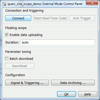
Next, click on the Signal & Triggering ... button under the Configuration category in the panel. The "Signal & Triggering" dialog looks similar to the following figure.
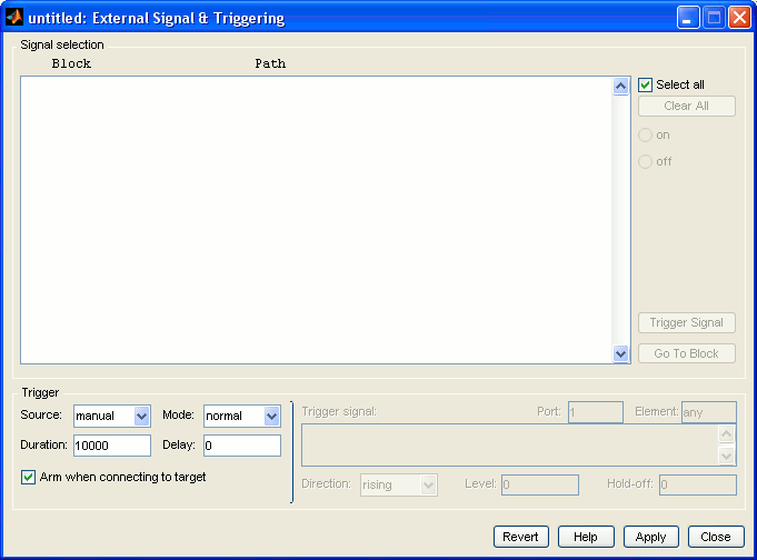
There are two sections in this dialog: Signal selection and Trigger. In the Signal selection section you select which signals to view during real-time execution and which signal is the trigger signal, if any. In the Trigger area you configure what constitutes a trigger event for the trigger signal selected in the Signal selection section. Below are the details of each section.
Signal selection
All external mode compatible blocks in your model appear in the Signal selection
list of the Signal & Triggering dialog. Examples of these blocks would be the "Scope"
and the "To Host File" blocks. In general, the blocks supporting signal triggering
will appear in this list. You use this list to select which blocks will collect
data from the real-time system. An X appears to the left of each selected
block's name. The Select all check box selects all
the signals. By default, the Select all option is
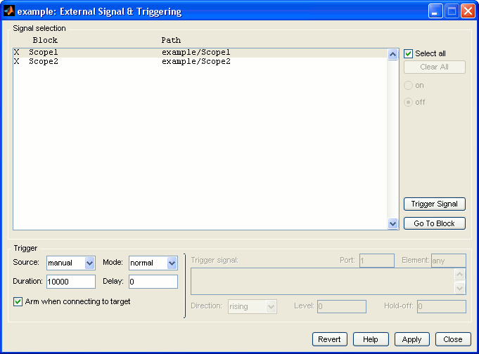
enabled. In the example shown below, there are two "Scope" blocks in the model and
they are both selected. Hence, both Scopes will be actively plotting the values
of their associated signals.
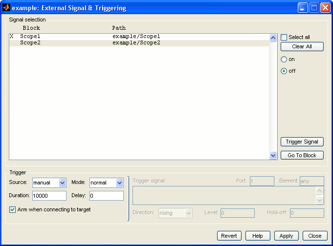
If the Select all option is unchecked, then you can manually enable or disable individual blocks using the on or off radio buttons respectively. You can also double-click on a block in the list to toggle between the selected state and unselected state. Below is an illustration of the same example but with Scope1 selected only. The Clear All button clears all the selections so that no block is enabled.
To configure a signal as being the trigger signal, click on the corresponding block
in the list and then click on the Trigger Signal button.
A T appears to the left of the block indicating that the signal is
now the trigger signal. The options in the Trigger section will apply to this signal
only. The trigger signal may be a vector, in which case a particular element of
that vector, or the entire vector may be used for the trigger event. The trigger
signal can be any of the signals attached as inputs to the selected block - which
input port should be the actual trigger signal is chosen in the Trigger section
of the Signal & Triggering dialog.
Note that it is possible to disable a block and still use its input as a trigger signal. In this case, the signal is used for determining when the trigger is armed, but the block which displays the trigger signal will be disabled. For example, you won't be able to view the trigger signal on a Scope in this case, but it will still be used for determining when the trigger is armed. The next figure illustrates this situation for the current example.
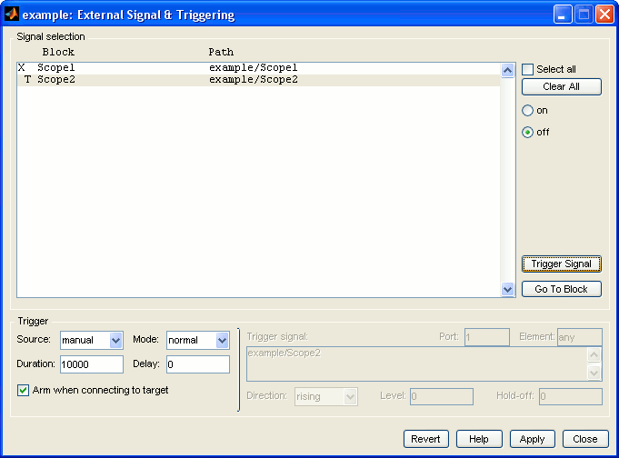
In this case, the signal connected to Scope2 acts as the trigger signal, but Scope2 itself will not plot the signal because it is disabled. The Go To Block button directs you to the location of the selected block in the model. Click on any of the blocks in the list and then click on this button to get redirected to that block's location in the model.
Trigger
The Trigger section is used to configure the trigger event. The following list enumerates the different trigger event parameters in this section.
Source: There are two choices for this parameter: signal and
manual. Selecting manual allows the Arm trigger button in the External Mode Control panel to be used to manually
arm and disarm the trigger. For more information on this button, please refer to
the Arming/Disarming the Trigger Signal section in this
document. If signal is selected then triggering is based on the trigger
signal. The trigger becomes armed when the conditions for the trigger event are
met by the trigger signal.
Mode: There are two choices: normal and one-shot.
In normal mode, the trigger is automatically rearmed each time a trigger
event occurs. In one-shot mode, only the first trigger event arms the
trigger. One buffer of data is collected each time you manually arm the trigger.
Duration: The number of base rate time steps for which external mode logs data after a trigger becomes fired (the base rate is the fastest sample rate in the model). For example, if the base rate of the model is 1 millisecond and a duration of 1000 samples is specified, then one second's worth of data will be collected. This parameter is similar to the Limit data points to last parameter of Scopes. The duration is used for real-time execution while the latter is used for normal simulation.
 Note in this example that if you set the stop time of the model to 1.0 seconds you
will need a Duration value of 1001 in order
to collect all the samples because the samples at time t=0.0 and t=1.0 are both
included in the data. Leaving the Duration at 1000 can result in only the
data at time t=1.0 being stored since Simulink does not maintain a circular buffer
- instead it restarts the buffer when the duration expires. Alternatively, set the
stop time to 0.999 seconds so that only 1000 data points need be collected.
Note in this example that if you set the stop time of the model to 1.0 seconds you
will need a Duration value of 1001 in order
to collect all the samples because the samples at time t=0.0 and t=1.0 are both
included in the data. Leaving the Duration at 1000 can result in only the
data at time t=1.0 being stored since Simulink does not maintain a circular buffer
- instead it restarts the buffer when the duration expires. Alternatively, set the
stop time to 0.999 seconds so that only 1000 data points need be collected.
Delay: Represents the amount of time that elapses between a trigger occurrence and the start of data collection. Like the duration, the delay is expressed in base rate steps, and can be positive or negative. A negative delay corresponds to pretriggering. When the delay is negative, data from the time preceding the trigger is collected.
Arm when connecting to target: If this parameter is selected, the trigger
is armed automatically as soon as you connect to the real-time code on the target.
If the trigger source is manual, the data collection begins immediately.
If the trigger source is signal, monitoring the trigger signal begins
and data is collected once the trigger is fired.
There is a line dividing the Trigger panel into two sub-sections. The parameters
to the left of the line are described above. The parameters to the right of the
line are disabled by default. In order to activate them, you need to switch the
trigger mode to signal. The next figure illustrates the "Signal & Triggering"
dialog with these parameters enabled.
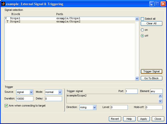
The parameters in this sub-section are the following:
Trigger signal: This area shows the name of the trigger signal selected using the Trigger Signal button in the Signal selection section. The above figure illustrates the case in which the input signal of the second "Scope" block is selected as the trigger signal. The name of that block is listed in the Trigger signal panel to indicate that it is the trigger signal.
Port: Specifies which input port of the block is connected to the trigger
signal. It accepts any number or the keyword last. The default value
is 1, meaning the first port is used. The signal connected to the specified
port will be treated as the trigger signal.
Element: Specifies which element of the trigger signal should be monitored
for trigger events, in the case where the signal is a vector. It accepts any number
or the keywords any and last. The default value is any,
meaning that all the elements of the trigger signal are monitored and a trigger
event occurs if any of the elements of the trigger signal meet the conditions of
the trigger.
Direction: Specifies the direction in which the signal must be traveling
when it crosses the threshold value in order to classify as a trigger event. There
are three choices: rising, falling and either.
The default is rising.
Level: This is the threshold value. The trigger signal must cross this value
in the designated direction to arm the trigger. By default, the level is 0.
Hold-off: The time between the termination of data collection and the rearming
of the trigger in response to a new trigger event. It only applies to normal
triggering mode and is expressed in base rate steps. A trigger event that occurs
during the hold-off period does not rearm the trigger.
Configuring the Trigger Event
This section provides information on how to set specific conditions for the trigger event to occur using the "Signal & Triggering" dialog discussed in the previous section. An example is used in this section with the Simulink diagram shown below:
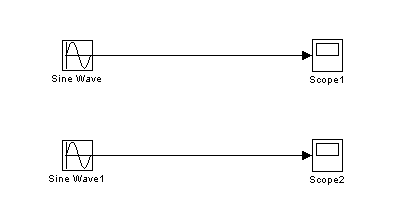
The first sine wave, called Sine Wave, has an amplitude of 10 and a frequency of 2*pi*0.5 rads/s. The second signal is called Sine Wave 1 and has an amplitude of 1 and a frequency of 2*pi*0.5 rads/s. We only want to view Sine Wave and use Sine Wave 1 as the trigger signal without viewing it on the "Scope2" window. The conditions for the trigger signal are the following:
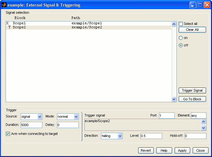
The threshold value to cross is 0.5 and the direction of the signal while crossing this threshold should be falling with no hold-off time.
The trigger mode should be normal so that data collection resumes each time the trigger signal falls below the specified threshold of 0.5. The duration should be set to 5000 samples, or 5 seconds at 1 kHz, and data collection should begin immediately once the trigger event occurs.
Please perform the following steps in order to set these conditions:
After creating the model shown above and configuring the model for external mode, go to the "Signal & Triggering" dialog in the External Mode Control Panel as discussed in the previous section.
In the Signal selection section, disable the Select all option. This enables the on and off radio buttons. Select "Scope1" in the list and click on the on button. Select the "Scope2" block and click on the Trigger Signal button to make it the trigger signal. Note that the signal is not selected for viewing since disabling the Select all option caused all the signals to be unselected by default. Below is a figure illustrating this situation.
Change the trigger source from manual to signal. Set the
trigger mode to normal. Set the duration of the trigger to 5000.
Leave the delay as it is. Enable Arm when connecting to target.. The dialog should now appear as shown below.

Leave the Port, Element
and Hold-off parameters as they are. Change
the threshold value to 0.5 and the direction in which the trigger signal
should be going while crossing the threshold to falling. The figure
below depicts this situation.
Click on Apply and then Close.
Build your model, open the two Scopes and run the real-time code in order to see the effects of signal triggering.
After running the model, notice that the "Scope2" block does not show anything since you have disabled it. The signal shown on "Scope1" should look similar to the following figure.
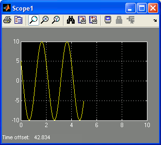
As you can see in the figure, the starting amplitude of the signal is at 5 and the direction of the signal is falling at that point. This occurs consistently because the trigger signal crosses the threshold value of 0.5 in the falling direction at the same time as the "Scope1" signal has an amplitude of 5. Thus, "Scope1" starts collecting data from its input signal when it has an amplitude of 5 because that is when the "Scope2" trigger signal fell below the specified threshold. Note, however, that this scenario only happens because the frequencies of the two signals are equal in this example.
Also observe that 5000 samples of data are collected. Since the sample rate of the model is 1 millisecond, 5 seconds of data are collected. This 5 seconds of data collection starts all over again each time the "Scope2" trigger signal cross the 0.5 threshold in the negative direction since we are using the normal trigger mode.
You can set different conditions and see how they change the behavior of data collection on the Scope. For example, change the trigger mode to one-shot, and the frequency of Sine Wave to twice the frequency of the trigger signal (that is 2*pi rads/s) and run your model. The data shown on "Scope1" block should now look similar to the figure below.
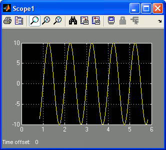
Notice that the Sine Wave signal has already passed the value 5 in the falling direction when the trigger signal crosses 0.5, because the frequency of Sine Wave is twice the frequency of the trigger signal. Sine Wave has actually changed direction and is now rising when the trigger event occurs.
Try more combinations and observe the effect of signal triggering on data collection on the Scope or
Arming/Disarming the Trigger Signal
You can manually arm or disarm the trigger signal while connected to the real-time code. The trigger signal is monitored for trigger events if you arm the trigger. Disarming the trigger disables monitoring of the trigger signal. Arming/disarming can be done using the External Mode Control panel. Below is an illustration of this panel.
The Arm Trigger button can be used to arm the trigger. Once you click on this button, it becomes a Cancel Trigger button, which is used to disarm the trigger. Notice that this button is not activated until you connect to the real-time code. Once you connect to the real-time code, the Arm/Cancel Trigger button becomes available as shown below.
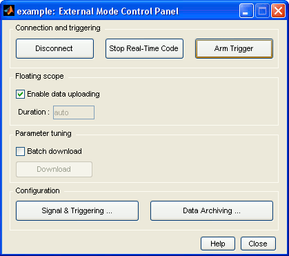
If the Arm when connecting to target option is selected, then the Cancel Trigger button is displayed when the real-time code is first run because the trigger is armed simply by connecting to the real-time code. Otherwise the Arm Trigger button is visible.
Note that once the trigger signal is armed, you cannot change parameters in the "Signal & Triggering" dialog. You have to wait until the trigger signal is disarmed if using one-shot trigger mode, or you must manually disarm the trigger if using the normal trigger mode in order to be able to make changes to the triggering parameters. For more information on the two trigger modes, please refer to the Signal & Triggering Dialog section in this document
Copyright ©2026 Quanser Inc. This page was generated 2026-05-13. Submit feedback to Quanser about this page.
Link to this page.