MATLAB Command Line
Click to copy the following command line to the clipboard. Then paste it in the MATLAB Command Window:
quarc_udp_supervisory_server_demo; quarc_udp_supervisory_client1_demo; quarc_udp_supervisory_client2_demoQUARC UDP Supervisory Demo
This example consists of three Simulink models: a server and two clients. It demonstrates how to use the Basic Communications blockset from the QUARC Targets Library to implement a UDP server capable of servicing multiple clients using UDP broadcasting. In this particular example, the server exchanges data with two clients at the same time. The clients must be run on separate remote hosts to execute properly. In other words, three systems are required to run this demonstration. This example is intended to illustrate the potential use of UDP for supervisory control in which there is one supervisor (the server) and multiple agents (the clients) being administered by the supervisor. For general information on the Basic Communications feature of QUARC, you can refer to the Basic Communications section. Be sure to investigate the Important Considerations section below to understand the design considerations that went into this demonstration.
Configuring the Demonstration
This demonstration must be run with the supervisory model (the server) on the local host and the two client models on separate remote targets communicating with the local host.
To run the clients on remote targets, some configuration is required. Specifically:
The steps outlined below assume that the remote targets are the same platform as the local host. If not then a different configuration must be activated in Model Explorer to correspond to the type of target running on each remote target.
To change the URI of each Stream Server block, double-click on the block to open its configuration dialog, as shown below.
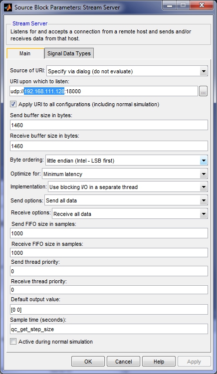
In the URI upon which to listen field, replace 192.168.111.128
in the URI with the host name or IP address of the host machine running the QUARC UDP Supervisory Server Demo model.
Click OK to close the configuration dialog.
To modify the model URI of a client so that the client model is run on the desired remote target, open the Configuration Parameters dialog by selecting from the menu, or by pressing Ctrl+E. Then navigate to the Code Generation/Interface pane in the Select treeview.
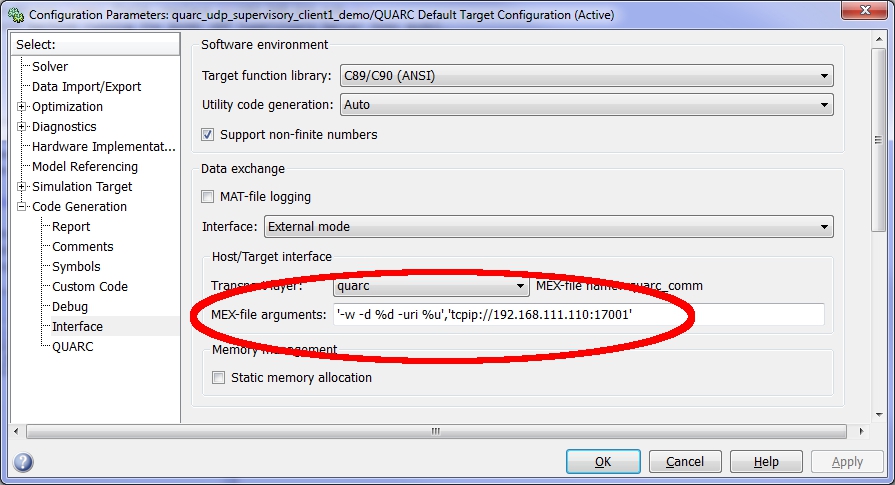
In the MEX-file arguments field, replace the model URI of the remote target in single quotes. Be sure to separate the model URI from the model arguments with a comma. For example, if the remote machine is called "remhost", then a suitable model URI is "tcpip://remhost:17001" and the MEX-file arguments would look like:
'-w -d %d -uri %u','tcpip://remhost:17001'
For more information on model URIs and running QUARC models on remote targets, please refer to the Specifying a Model and/or Target URI page in the QUARC documentation. For a general discussion of model URIs, refer to Real-Time Code - the Model URI section of the Communicating with the Target documentation.
Configure the Stream Server block and model URI of each client model. Don't forget the firewall exceptions for UDP port 18000 and TCP ports 17000 and 17001.
Demonstration
Select from the menu of the diagram, or press Ctrl+B while each of the diagrams is the active window. A great deal of output will appear in the Diagnostic Viewer about the progress of the build. If you cannot see the Diagnostic Viewer, you can open it by selecting from the menu of the diagram, or clicking on the View Diagnostics hyperlink at the bottom of the diagram. If you have MATLAB R2013b or earlier then the output will appear in the MATLAB Command Window.
Double-click on the "Server Data" Scope in the quarc_udp_supervisory_client1_demo.mdl and quarc_udp_supervisory_client2_demo.mdl models to open their Scopes.
Double-click on the "Server Data", "Client 1 Data" and "Client 2 Data" Scopes in the quarc_udp_supervisory_server_demo.mdl model to open its Scopes.
Click on the button or select from the menu of the quarc_udp_supervisory_server_demo.mdl diagram to connect to the server model.
Start the server model by clicking on the button or selecting from the menu of the diagram. The item of the menu may also be used to both connect and start the model in one operation.
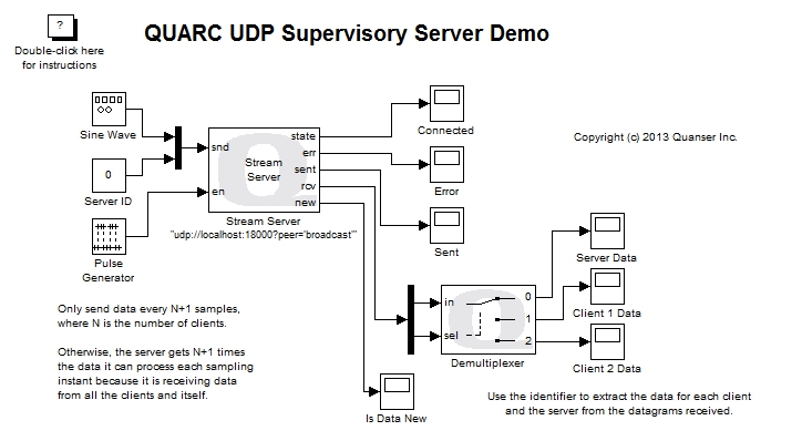
At this point, only the server is running. No clients are executing. However, the "Server Data" plot shows the sine wave transmitted by the server. Unlike the "QUARC UDP Server Demo", in this example the server receives its own data! Because the server is operating in UDP broadcast mode, each datagram it sends gets broadcast to the whole network and received by every server listening on the port - including the server which sent the datagram in the first place. The logic for the models must account for this behaviour when UDP broadcast is used.

Now start each of the client models.
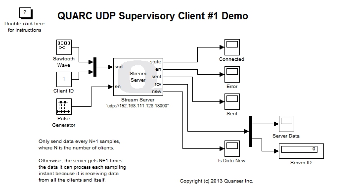
A sine wave of amplitude 4 will appear in the "Server Data" Scope of the two clients.
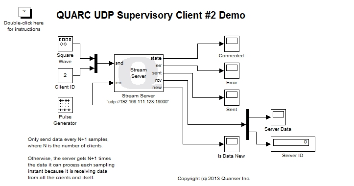
The server model receives a sawtooth wave from client #1 and a square wave from client #2.
Click on the button or select from the menu of the diagram to stop each model. The item of the menu may also be used.
Important Considerations
A number of important decisions were made in designing this demonstration to ensure that communications with multiple clients operated correctly. This section deals with the important factors that were considered and drove the implementation of this example. It will also highlight changes from the default settings that were required.
Use of Stream Server block for Clients
Unlike the QUARC UDP Server Demo, this example uses the Stream Server block in the client models instead of the Stream Client block. At first, this implementation appears very counter-intuitive.
However, the reasoning is actually not that complicated. The quarc_udp_supervisory_server_demo.mdl model broadcasts UDP datagrams to the network using a special broadcast address. It does not communicate using the IP address of each client. However, UDP clients only receive datagrams sent to their IP address. Thus, using a Stream Client would not allow the client to receive any datagrams from the server because the broadcast address would not match the IP address of the client socket. The Stream Client block would still be able to send data to the server, however, because the client sends the datagrams to the server machine and the Stream Server block accepts any datagrams sent to its port.
By using a Stream Server block in each client model, each client can receive any datagrams sent to the same port, regardless whether the IP address is a broadcast address or not. Thus, the Stream Server block in the client can receive the data broadcast by the server.
The hostname or IP address of the server machine is specified in the URI of the Stream Server block for each client. Doing so causes it to transmit its datagrams to that address regardless of the IP addresses associated with any datagrams it receives. Hence, the Stream Server block in the client also allows the client to send data to the server.
As a result, by using a Stream Server block in each client, the client can both send and receive data from the QUARC UDP Supervisory Server Demo model.
Another way to look at this topology is that every model is a server running on its own machine. The servers running on the client machines are configured to always send their datagrams to the machine running the quarc_udp_supervisory_server_demo.mdl model, while the server running on that machine is configured to broadcast its datagrams to everyone. This understanding justifies the requirement that each model be running on its own machine so that there is only one server on each machine and conflicts between servers listening on the same port are avoided.
Peer Setting on the Server URI
The URI of the Stream Server block in the quarc_udp_supervisory_server_demo model has an additional option that is not part of the default settings. The peer option has been changed from the default to the value broadcast.
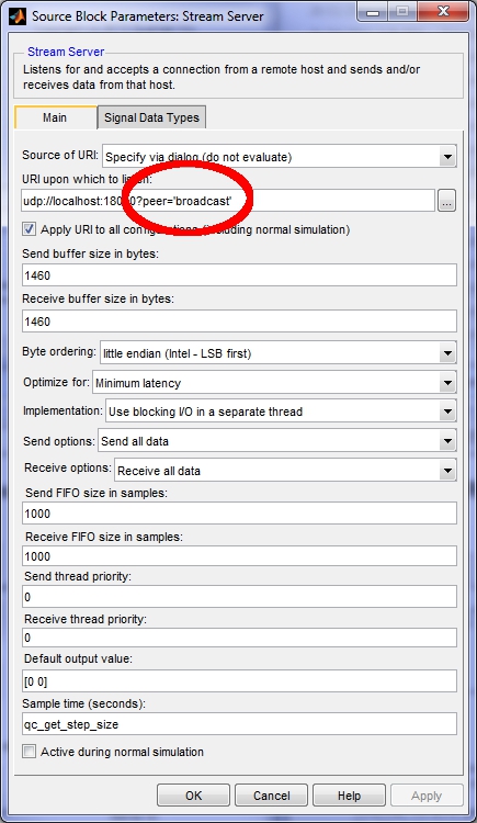
When the peer option is set to broadcast the UDP protocol allows datagrams from any client to be received by the server. The default value of this option is one, which only accepts datagrams from the first client to communicate with the server. The default is one because it is assumed that the most common paradigm is only two models communicating.
With the peer option set to broadcast, the UDP server sends a special type of datagram when transmitting data that is broadcast to every computer on the network. Using UDP broadcast is an efficient way for the server to communicate with multiple clients because it does not have to transmit a separate datagram for each client.
Blocking I/O for the Stream Server
The default setting for the Implementation parameter of the Stream Server block in the server is . Unlike the QUARC UDP Server Demo, this default does not need to be changed because client starvation cannot occur in UDP broadcast mode. Clients cannot be starved for data because the server broadcasts every datagram to every client. The non-blocking I/O implementation could be used as well.
Decimating the Client and Server Data
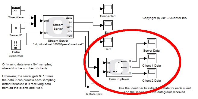
All three models run at the same sampling rate. Let the sampling rate be Ts. The Stream Server is receiving data from both clients at the same time, as well as from itself. If both clients were sending data at the sampling rate Ts then the server would be receiving three UDP datagrams every sampling instant: one from each of the two clients and one from itself. However, the Stream Server block is only reading one datagram at a time from the stream. It can only read one datagram every Ts seconds, not three. If both clients were sending data every Ts seconds then the Stream Server block would not be able to keep up with the data from the clients and itself.
To avoid overwhelming the server with data, each client decimates the data it sends to the server. The server also decimates the data it transmits. This decimation is accomplished using a Pulse Generator block connected to the en input of the Stream Server blocks.
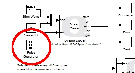
The Pulse Generator is configured to produce a pulse every N+1 sampling instants, where N is the number of clients. In this case there are only two clients, so N is 2, and the Pulse Generator produces a pulse every third sampling instant. Notice that this decimation is different from the QUARC UDP Server Demo.
As a result, the server and each client are sending data every (N+1)*Ts seconds and the server receives a datagram every Ts seconds on average. The Stream Server block is not overwhelmed with data. Since the server decimates the data it sends, each client will also receive decimated data. Each client will receive data every (N+1)*Ts seconds on average, just like the data received by the server for each client.
A natural question is why the Stream Server block should only process one datagram at a time. Why not configure it to receive N+1 datagrams at a time, and then the N clients will not need to decimate their data? The problem with this solution is that not all clients may be running. For example, if the user stops one of the clients then the server will no longer be receiving N+1 datagrams each sampling instant. Hence, it will have to wait for another sampling instant before it has a full N+1 datagrams and can output anything from its rcv port. Since it is not uncommon for a client not to be running, particularly when the topology is started up or shut down, this situation will occur and is not ideal. It can however be detected by monitoring the new output of the Stream Server block.
Another possible alternative is to place the Stream Server block in a For Iterator Subsystem which executes N+1 times and have it only transmit on the first iteration (so it doesn't send itself and every client N+1 datagrams). The loop could be aborted if the new output was false. This solution may effectively resolve the decimation issue but was not attempted for this example because of the added complexity.
Client and Server Identifiers
The Stream Server block does not provide any mechanism for knowing the IP address associated with each datagram received since it is a generic Stream block used for any communications protocol. As a result, the server cannot use the IP address to distinguish between the data sent from each client. In reality, an IP address is an inconvenient quantity anyways, as IP addresses are often dynamically assigned by DHCP.
To enable the server to associate each datagram with a particular client, an identifier value was added to the data sent by each client, as well as to the data sent by the server. The Server ID was not technically necessary, but was added for completeness because of its beneficial use in other UDP examples.
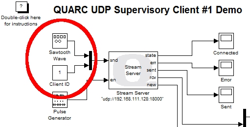
The above figure shows the client identifier being muxed into the data sent to the server. The server uses this identifier to route the client's data to its own Scope via a Demultiplexer block. The Demultiplexer block acts like a digital demultiplexer and routes its input signal to one of N outputs based on the selection input. The client identifier is passed to the selection input to route the data received to the appropriate plot.
Running the example on a different target
To run the example on a different target, refer to the instructions on the Running QUARC Examples on Remote Targets page.
Copyright ©2026 Quanser Inc. This page was generated 2026-05-13. Submit feedback to Quanser about this page.
Link to this page.