
Fieldbus
Industrial automation applications often require highly distributed I/O, in which an industrial PC controls systems that stretch across the factory floor. The technology of choice for such distributed I/O is fieldbus technology. Quanser's industrial arm his tackling these demanding applications by adding support for fieldbus technology to QUARC.
Field this technology exists in a myriad of forms. One of the emerging forms of fieldbus technology is industrial ethernet, which allows an ethernet cable to be used to connect distributed fieldbus modules across the factory floor. An exciting new industrial ethernet technology is EtherCAT, originally introduced by Bechkoff Automation.
EtherCAT technology allows a standard network interface card (NIC) to be used to control industrial machinery. It makes optimal use of ethernet packets through a custom ethernet protocol based on the notion of a "fieldbus memory". The "slave" devices connected to the ethernet cable are mapped into a global 4 GB "memory" space. Any bit within that memory space may be addressed by the PC - the EtherCAT master. EtherCAT packets are capable of reading to and writing from a block of data in that memory space, even if it crosses device boundaries, thereby allowing a single ethernet packet to be used to read or write to multiple slave devices simultaneously. In fact, multiple EtherCAT commands or "telegrams" may be packed into a single ethernet packet! Furthermore, ASIC devices on the slaves process the ethernet packets on-the-fly, without waiting for the slave microprocessor to respond. Thus, EtherCAT is designed to optimize the use of the network bandwidth and can achieve high data rates.
 QUARC currently only supports EtherCAT technology on its QNX x86 target. While Quanser does have a functioning EtherCAT
stack for Windows, it is not provided with QUARC and EtherCAT is not supported by the QUARC Windows Target.
QUARC currently only supports EtherCAT technology on its QNX x86 target. While Quanser does have a functioning EtherCAT
stack for Windows, it is not provided with QUARC and EtherCAT is not supported by the QUARC Windows Target.
QUARC's support for EtherCAT fieldbus technology is currently limited. An EtherCAT Master may be added to a Simulink model using the EtherCAT Master block. The EtherCAT Master block requires an XML configuration file to configure the EtherCAT stack. The XML configuration file determines exactly what EtherCAT commands will be sent to transition between the states of the master and slave devices, and what commands will be sent on a regular basis i.e., cyclic commands. QUARC does not currently supply a tool for creating the XML configuration file. However, it may be generated using third party tools such as the TwinCAT I/O Manager from Beckhoff. Refer to the section on TwinCAT™ below for information on how to create an XML configuration file from TwinCAT.
The EtherCAT Master block communicates with Quanser's EtherCAT stack. This stack is loaded as part of the io-net network subsystem when the machine is booted. The stack, however, does not run until an EtherCAT Master block requests an EtherCAT stack. Thus, the priority of the EtherCAT stack threads and its sampling rate may be set from the parameters of the EtherCAT Master block via the Stack sample time parameter.
The EtherCAT stack supports two types of protocols: UDP or EtherCAT. The UDP protocol is useful when using EtherCAT slaves devices over a standard network, but it has much slower performance and more variability in the data rate. The EtherCAT protocol is a custom Ethernet protocol and delivers the highest performance and best utilitization of the network bandwidth. However, the EtherCAT protocol cannot be used on a shared network - it is meant for an Ethernet network exclusively reserved for EtherCAT devices.
The EtherCAT Master block can be configured to initialize the EtherCAT master and slaves into a predefined state. This initial state is typically set to the Operational state so that all the devices are fully operational once the stack has completed its initialization sequence (defined in the XML configuration file).
QUARC's EtherCAT blocks are currently designed to work with the EtherCAT process image - the 4GB virtual address space assigned to the slave devices on an EtherCAT segment, also known as the fieldbus memory. The EtherCAT Read and EtherCAT Write blocks may be used to read and write from the process image. Any number of these blocks may be placed in the model, including at different sample rates, but it is most efficient to minimize the number of blocks used. The EtherCAT Read and EtherCAT Write blocks allow you to specify which process variables will be read or written. The definitions of the process variables are read from the XML configuration file passed to the EtherCAT Master block. Each block is capable of reading or writing a set of process variables rather than a single process variable within the process image. The list of variables is compiled by selecting a variable from the drop-down list in the block's parameters and clicking the button. To remove a variable from the list, choose the variable from the compiled list of variables and then click on the button. The size and data type of the selected process variable is displayed by the block for the user's convenience.
Using TwinCAT to Generate an XML Configuration File
TwinCAT™ is an industrial automation package provided by Bechkoff Automation. It does not support Simulink and is designed around an entirely different paradigm for industrial control. While TwinCAT is not intended as the final vehicle for creating XML configuration files for the EtherCAT Master block, it may be used for this purpose. This section provides a brief explanation of how to create an XML configuration file using TwinCAT.
The first step is to download and install TwinCAT from the Bechkhoff website, https://www.beckhoff.com/ on a Windows machine. TwinCat is not free, but may be downloaded as a 30-day trial version. Only the TwinCAT I/O Manager (also called the TwinCAT System Manager) is required.
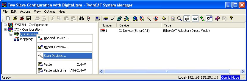
Connect your EtherCAT segment to the network interface card (NIC) of the Windows machine where TwinCAT installed. Run the TwinCAT System Manager. Right-click on the I/O Devices item in the treeview and select from the context menu, as illustrated below. This option should scan the EtherCAT segment and create devices for each slave on the segment.
Devices and "boxes" may be added manually to the hierarchy using the and context menu items. A "box" is one EtherCAT terminal, such as the EL4132 Analog Output Terminal, or EL5101 Encoder Terminal, both offered by Bechkhoff. Boxes are appended to devices such as the EtherCAT Adapter (Direct Mode) device. A sample hierarchy is shown below, in which there are two EK1100 System Couplers, each with terminals attached to it for a total of seven terminals. The first EK1100 System Coupler has three terminals attached to it: an EL4132 Analog Output Terminal, an EL3102 Analog Input Terminal and an EL9011 End Terminal (which is essentially just a face plate to cover the interconnects). The second EK1100 System Coupler has four terminals attached to it: an EL5101 Encoder Terminal, an EL2008 Digital Output Terminal, an EL1008 Digital Input Terminal, and finally another EL9011 End Terminal.
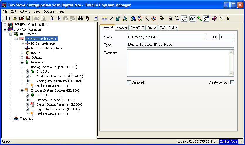
Once the configuration of the EtherCAT segment has been entered in TwinCAT, it is now possible to generate an XML configuration file corresponding to that configuration. Click on the EtherCAT Adapter device in the I/O Devices hierarchy. In the above example, it is the item. A set of tabbed panes will appear to the right of the treeview, as illustrated above, for the device. Click on the EtherCAT tab. The EtherCAT pane for our example is depicted below.
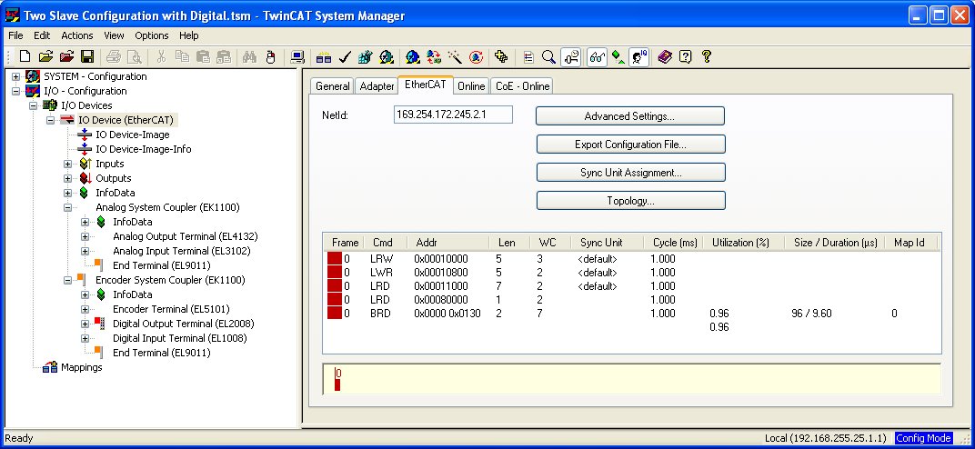
In the EtherCAT pane for the device, click on the button to export the configuration as an XML file. A Save As dialog will open, in which you simply specify the name of the XML configuration file to create. Enter a file name and click to create the XML configuration file. For early versions of TwinCAT, it was necessary to edit the first line of the generated XML file and change it to:
<?xml version="1.0" encoding="ISO-8859-1"?>
In particular, the encoding used to be saved as "ISO8859-1" instead of "ISO-8859-1", but this bug has now been fixed. Hence, it should no longer be necessary to edit the XML configuration file. Simply put the XML configuration file in the MATLAB path and enter its name in the EtherCAT Master block's XML file parameter.
Copyright ©2026 Quanser Inc. This page was generated 2026-05-13. Submit feedback to Quanser about this page.
Link to this page.