
Quanser Qube-Servo 3
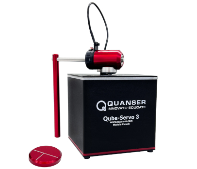
The Quanser Qube-Servo 3 is an integrated DC-servo motor experiment. It is designed to help teach fundamental control concepts and theories on an easy-to-use and intuitive platform. For more information, visit Quanser Qube-Servo3
The QUARC driver name for this card is qube_servo3_usb.
To select the Quanser Qube-Servo 3 HIL board, select the QUARC qube_servo3_usb board type from the drop-down list on the Main tab of the HIL Initialize block.
The Quanser Qube-Servo 3 I/O channels are described below.
Clocks
There are currently no configuration options for the Quanser Qube-Servo 3 clocks.
Analog Inputs
The Quanser Qube-Servo 3 supports one analog input, which is channel zero. The analog input measures the current to the motor in Amperes. Its maximum range is ±3A.
Analog Outputs
The Quanser Qube-Servo 3 supports one analog output, which is channel zero. The analog output drives the motor voltage. Its maximum range is ±15V. The pwm_en board specific option must not be set in order to use analog output on this card.
Digital Inputs
The Quanser Qube-Servo 3 supports three digital inputs, which are used for diagnostics. The digital inputs are enumerated in the table below.
|
Channel |
Description |
|---|---|
|
0 |
Amplifier fault. If the amplifer is enabled and this fault occurs, the amplifier may be experiencing excessive temperatures and shut down to protect itself. |
|
1 |
Motor stall detected. Occurs when the motor is stalled or excessively slowed and the applied voltage (including deadband compensation) is greater than 5V. |
|
2 |
Motor stall error. When a stall warning has been asserted continuously for approximately 3s. |
Digital Outputs
The Quanser Qube-Servo 3 supports one digital output, which is channel zero. The digital output acts as an enable for the motor drive circuitry. When this output is low, the motor amplifier is disabled. When it is high, the motor amplifier is enabled.
The Quanser Qube-Servo 3 has internal stall detection and once a stall error is asserted, the amplifier is automatically disables itself. The card can be re-enabled by setting the output low then high again.
| Note: Constantly resetting the amplifier whenever a stall-error occurs can result in excessive heat being generated by the motor potentially causing damage. |
Encoder Inputs
The Quanser Qube-Servo 3 supports two encoder inputs. Both channels provide 24-bit count values. These two channels only support 4X quadrature mode. The encoder channels are enumerated in the table below:
|
Channel |
Description |
|---|---|
|
0 |
Motor position |
|
1 |
Encoder 1 position (typically used for the inverted pendulum) |
In order to set the encoder counters to a particular count when the model is loaded, the encoder inputs must
be configured on the HIL Initialize
block's Encoder Inputs tab. Set the Encoder input channels
field to all the encoder channels that will be
used on the board for the current diagram. For example, enter
0:1
to
indicate channels 0 through 1 are used as encoder inputs.
The first two encoder inputs are sampled simultaneously when measured using a single HIL Read block.
PWM Outputs
The Quanser Qube-Servo 3 driver supports one PWM output channel, which is channel 0. Its maximum range is ±1 mapping to ±24V. Note, however, that the Quanser Qube-Servo 3 internally limits the output voltage to 15V or a corresponding PWM value of 0.625. The pwm_en board specific option must be set in order to use PWM output on this card.
The PWM mode, frequency or configurations are fixed and cannot be modified.
| Note that deadband compensation is not used in the PWM mode. |
Other Inputs
The Quanser Qube-Servo 3 supports two other input channels, which are 32-bit digital tachometer readings based on a 72MHz counter. The other input channels are enumberated in the table below:
|
Channel |
Description |
|---|---|
|
14000 |
Motor velocity |
|
14001 |
Encoder 1 velocity (typically used for the inverted pendulum) |
The units are counts/s.
Channel numbers for Other Input or Output channels use predefined ranges for each type of measurement to ensure consistency between data acquisition devices. Refer to QUARC Other Channels for a list of the Other Input or Output channel number ranges defined for any HIL Data Acquisition Card and their SI units.
Other Outputs
The Quanser Qube-Servo 3 supports three other output channels, allowing the color of the LED panel to be controlled. Note that each channel supports fractional values between 0 and 1, allowing full RGB color. Refer to the table below for a list of the channels:
|
Channel |
Description |
Range |
|---|---|---|
|
11000 |
Red component for LED color |
0 to 1 |
|
11001 |
Green component for LED color |
0 to 1 |
|
11002 |
Blue component for LED color |
0 to 1 |
Channel numbers for Other Input or Output channels use predefined ranges for each type of measurement to ensure consistency between data acquisition devices. Refer to QUARC Other Channels for a list of the Other Input or Output channel number ranges defined for any HIL Data Acquisition Card and their SI units.
Interrupts
The Quanser Qube-Servo 3 card, or its driver, does not support any interrupt sources.
Watchdog
The Quanser Qube-Servo 3 supports a watchdog timer for resetting the outputs on watchdog expiry. Namely, the analog, digital and other output channels will be reset to the user-defined values on watchdog expiry. Resetting of the outputs occurs without software intervention, and therefore may be used as a safety mechanism in the event of software failure.
To enable the watchdog, place a HIL Watchdog block in the diagram.
To configure the values to which the output channels are reset on watchdog expiry, set the corresponding fields in the Analog Outputs, Digital Outputs and Other Outputs tabs of the HIL Initialize block.
Once the watchdog has expired, further I/O on the outputs is disabled until the watchdog state is cleared.
Use a HIL Watchdog Clear block to clear the watchdog state when the model is running. Restarting the model will also clear the watchdog state.
Board-Specific Options
The Quanser Qube-Servo 3 has a number of board-specific options to control specialized functionality of the card and compensate for nonlinear factors to create a near-ideal motor response.
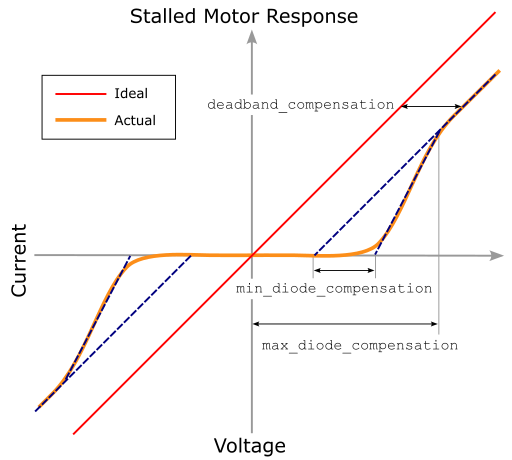
deadband_compensation
This option offsets the motor command by the specified voltage multiplied by the sign of the applied voltage to compensate for amplifier deadband. At zero
volts, no offset is applied. The default value is deadband_compensation=0.3. This option is only available for analog outputs and will be ignored
if the pwm_en option is used. This parameter can be tuned on a per-device basis by stalling the motor, sweeping the voltage from -10V to +10V
and observing the offset of the current measurement from a linear line of the same slope that is a function of the motor resistance. Note that the sweep should be
faster than 3s to avoid a stall error.
min_diode_compensation
Internal protection diodes create a small, non-linear effect near zero. This effect can be removed with the diode compensation factors. After determining
the deadband compensation at the the +/-10V range, stall the motor and sweep the voltage from -10V to +10V while observing the current measurement. Any
remaining "deadband" near the zero crossing is removed by the min_diode_compensation value. The effect diminishes linearly to the value of
max_diode_compensation value. The default value is min_diode_compensation=0.3. The value must be great or equal to zero and less
than max_diode_compensation value to be active. This option is only available for analog outputs and will be ignored if the pwm_en
option is used.
max_diode_compensation
Internal protection diodes create a small, non-linear effect near zero. This effect can be removed with the diode compensation factors. After determining
the deadband compensation at the the +/-10V range, stall the motor and sweep the voltage from -10V to +10V while observing the current measurement. Any
remaining "deadband" near the zero crossing is removed by the min_diode_compensation value. The effect diminishes linearly to the value of
max_diode_compensation value. The default value is max_diode_compensation=1.5. The value must be great or equal to zero and greater
than min_diode_compensation value to be active. This option is only available for analog outputs and will be ignored if the pwm_en
option is used.
pwm_en
Set this option to "yes", "y", or "1" to enable control of the motor using PWM command.
| When this option is set, the analog output cannot be used. All references to setting initial and final outputs must be removed. In Simulink, in the HIL Initialize block on the Analog Outputs tab, change the Analog Output Channels from [0] to []. On the PWM Outputs tab change the PWM Output Channels from [] to [0]. Also note that deadband compensation is disabled and any user-specified value in the board-specific options will be ignored. |
enc0_velocity
Set this option to the minimum velocity in counts per second that should be detected by the motor digital tachometer. This limit
is an artificial limit that is useful when friction stops the device long before it reaches the slowest detectable velocity of
the Quanser Qube-Servo 3 hardware. If this option is set to zero then the slowest velocity measurable by the hardware is used. The default
value is enc0_velocity=3.0 which disables the clamping function.
enc1_velocity
Set this option to the minimum velocity in counts per second that should be detected by the pendulum digital tachometer. This limit
is an artificial limit that is useful when friction stops the device long before it reaches the slowest detectable velocity of
the Quanser Qube-Servo 3 hardware. If this option is set to zero then the slowest velocity measurable by the hardware is used. The default
value is enc1_velocity=3.0 which disables the clamping function.
Properties
The Quanser Qube-Servo 3 driver currently supports the following read-only properties:
|
Property |
Type |
Description |
|---|---|---|
|
PROPERTY_INTEGER_VENDOR_ID |
Integer |
Vendor identifier associated with the hardware |
|
PROPERTY_INTEGER_PRODUCT_ID |
Integer |
Product identifier associated with the hardware |
|
PROPERTY_INTEGER_FIRMWARE_MAJOR_VERSION |
Integer |
Major version number of the firmware (hardware) |
|
PROPERTY_INTEGER_FIRMWARE_MINOR_VERSION |
Integer |
Minor version number of the firmware (Qube interface) |
|
PROPERTY_INTEGER_FIRMWARE_BUILD |
Integer |
Build number of the firmware (currently always zero) |
|
PROPERTY_INTEGER_HARDWARE_VERSION |
Integer |
Revision number of the firmware (currently always zero) |
|
PROPERTY_STRING_MANUFACTURER |
String |
Manufacturer of the device |
|
PROPERTY_STRING_PRODUCT_NAME |
String |
Product name of the device |
|
PROPERTY_STRING_MODEL_NAME |
String |
Model name of the device |
|
PROPERTY_STRING_SERIAL_NUMBER |
String |
Serial number of the device |
|
PROPERTY_STRING_FIRMWARE_VERSION |
String |
Firmware version of the PC interface |
Targets
|
Target |
Supported |
Comments |
|---|---|---|
|
Yes |
Fully supported. |
|
|
Yes |
Fully supported. |
|
|
No |
Not supported. |
|
|
No |
Not supported. |
|
|
No |
Not supported. |
|
|
No |
Not supported. |
|
|
No |
Not supported. |
|
|
No |
Not supported. |
|
|
No |
Not supported. |
|
|
No |
Not supported. |
|
|
No |
Not supported. |
|
|
No |
Not supported. |
|
|
No |
Not supported. |
|
|
No |
Not supported. |
|
|
No |
Not supported. |
|
|
Rapid Simulation (RSIM) Target |
Yes |
Supported with no communication to the hardware. |
|
Normal simulation |
Yes |
Supported with no communication to the hardware. |
See Also
Copyright ©2026 Quanser Inc. This page was generated 2026-05-13. Submit feedback to Quanser about this page.
Link to this page.
