
Video3D Simulation
Simulates an RGBD camera.
Library
QUARC Targets/Multimedia MATLAB Command Line Click to copy the following command line to the clipboard. Then paste it in the MATLAB Command Window: qc_open_library('quarc_library/Multimedia')
Description
The Video3D Simulation block simulates an RGBD camera for use by the Video3D blocks.
The block is able to simulate depth, RGB, infrared and fisheye camera sensors as well as gyroscope, accelerometer and pose motion sensors. Sensor data is fed to the inputs of the block and this sensor data is propagated to any clients which are using the simulated device.
The Video3D Simulation block listens on the URI specified in the dialog parameters. Any clients which connect to that URI will be able to use the simulated device. The Device identifier parameter provides the device identifier to use for the device.
To use the simulated RGDB camera from the Video3D blocks, simply add the URI preceded by an '@' character to the Device identifier field of the Video3D Initialize block. For example, instead of specifying a Device identifier of "0", enter an identifier of "0@tcpip://camhost:18001", where the Video3D Simulation block is running in a model on the machine "camhost" and serving on port 18001. Other than this small change, the simulated camera should be indistinguishable from an actual device.
The URI may be specified in the dialog parameters or via an input port. Which option is used is determined by the Source of URI parameter. When the URI is specified via an input, the input is typically driven by a Model Argument block, which allows a model argument to be used to assign the URI at runtime.
| If the URI is specified via an input port, the Video3D Simulation block only samples the input when the model is first started. Hence, the URI cannot be changed while the model is running. |
Helpful Hints
Firewall
 If remote clients will be communicating with the Video3D Simulation then be sure to configure the server machine's firewall
to allow incoming access on the port being used.
If remote clients will be communicating with the Video3D Simulation then be sure to configure the server machine's firewall
to allow incoming access on the port being used.
Input Ports
d1..dN
The depth images for depth streams 1..N, where 1..N are the stream indices specified in the Stream indices parameter on the Depth tab of the dialog parameters. Depth images are typically MATLAB greyscale images (HxW) with a data type of uint16. The input image must be either a MATLAB RGB or MATLAB grayscale image. The image will be converted to whatever format, data type and resolution is required by the Video3D Capture block using the simulated camera.
Each port inherits its own sample time. The frame rate will also be converted to match the frame rate requested by the Video3D Capture block using the simulated camera.
rgb1..rgbN
The RGB images for RGB streams 1..N, where 1..N are the stream indices specified in the Stream indices parameter on the RGB tab of the dialog parameters. RGB images are typically MATLAB RGB images (HxWx3) with a data type of uint8. The input image must be either a MATLAB RGB or MATLAB grayscale image. The image will be converted to whatever format, data type and resolution is required by the Video3D Capture block using the simulated camera.
Each port inherits its own sample time. The frame rate will also be converted to match the frame rate requested by the Video3D Capture block using the simulated camera.
i1..iN
The infrared images for infrared streams 1..N, where 1..N are the stream indices specified in the Stream indices parameter on the Infrared tab of the dialog parameters. Infrared images are typically MATLAB greyscale images (HxW) with a data type of uint8. The input image must be either a MATLAB RGB or MATLAB grayscale image. The image will be converted to whatever format, data type and resolution is required by the Video3D Capture block using the simulated camera.
Each port inherits its own sample time. The frame rate will also be converted to match the frame rate requested by the Video3D Capture block using the simulated camera.
f1..fN
The fisheye images for fisheye streams 1..N, where 1..N are the stream indices specified in the Stream indices parameter on the Fisheye tab of the dialog parameters. Fisheye images are typically MATLAB greyscale images (HxW) with a data type of uint8. The input image must be either a MATLAB RGB or MATLAB grayscale image. The image will be converted to whatever format, data type and resolution is required by the Video3D Capture block using the simulated camera.
Each port inherits its own sample time. The frame rate will also be converted to match the frame rate requested by the Video3D Capture block using the simulated camera.
g1..gN
The gyroscope motion data for gyroscope streams 1..N, where 1..N are the stream indices specified in the Stream indices parameter on the Gyroscope tab of the dialog parameters. Gyroscope motion data must be a 3-vector of single elements in SI units. Each port inherits its own sample time.
a1..aN
The accelerometer motion data for accelerometer streams 1..N, where 1..N are the stream indices specified in the Stream indices parameter on the Accelerometer tab of the dialog parameters. Accelerometer motion data must be a 3-vector of single elements in SI units. Each port inherits its own sample time.
p1..pN
The pose motion data for pose streams 1..N, where 1..N are the stream indices specified in the Stream indices parameter on the Pose tab of the dialog parameters. Pose motion data must be a 6-vector of single elements in SI units representing position and orientation. Each port inherits its own sample time.
uri
A string specifying the URI upon which to listen and service client connections. The string
must be a null-terminated vector of characters represented as a vector of uint8 quantities.
It may be variable-sized. This string is typically provided either directly or indirectly by a
Model Argument
block or String Constant block.
This input is only available if the Source of URI parameter is
set to External input port. Refer to the documentation below on the
Source of URI parameter for details.
Output Ports
d1?..dN?
Optional boolean outputs indicating whether the associated depth input stream is actually being used by a client. There is one output for each depth stream specified in the Stream indices parameter on the Depth tab of the dialog parameters. This parameter is only present if the Show streams in use option is checked.
rgb1?..rgbN?
Optional boolean outputs indicating whether the associated RGB input stream is actually being used by a client. There is one output for each RGB stream specified in the Stream indices parameter on the RGB tab of the dialog parameters. This parameter is only present if the Show streams in use option is checked.
i1?..iN?
Optional boolean outputs indicating whether the associated infrared input stream is actually being used by a client. There is one output for each infrared stream specified in the Stream indices parameter on the Infrared tab of the dialog parameters. This port is only present if the Show streams in use option is checked.
f1?..fN?
Optional boolean outputs indicating whether the associated fisheye input stream is actually being used by a client. There is one output for each fisheye stream specified in the Stream indices parameter on the Fisheye tab of the dialog parameters. This port is only present if the Show streams in use option is checked.
g1?..gN?
Optional boolean outputs indicating whether the associated gyroscope input stream is actually being used by a client. There is one output for each gyroscope stream specified in the Stream indices parameter on the Gyroscope tab of the dialog parameters. This port is only present if the Show streams in use option is checked.
a1?..aN?
Optional boolean outputs indicating whether the associated accelerometer input stream is actually being used by a client. There is one output for each accelerometer stream specified in the Stream indices parameter on the Accelerometer tab of the dialog parameters. This port is only present if the Show streams in use option is checked.
p1?..pN?
Optional boolean outputs indicating whether the associated pose input stream is actually being used by a client. There is one output for each pose stream specified in the Stream indices parameter on the Pose tab of the dialog parameters. This port is only present if the Show streams in use option is checked.
err
The current error status of the simulation. The sample time of this port is specified in the Output sample time parameter.
Parameters and Dialog Box
Main Pane
The Main pane of the dialog appears as follows:
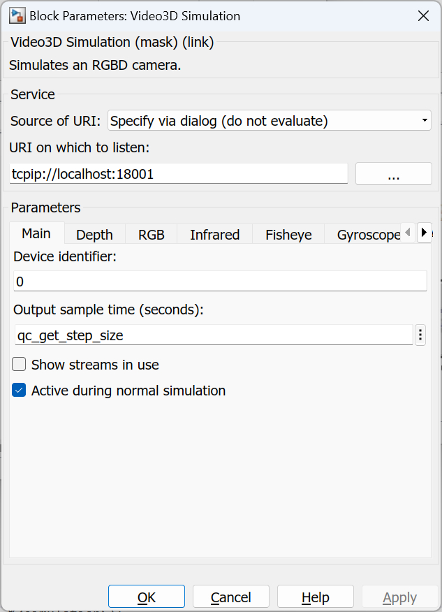
Source of URI
Indicates whether the URI should be determined from the dialog parameters or an
input port. If this field is set to Specify via dialog (do not evaluate) then
the URI is specified via the URI upon which to listen
parameter. In this case, the URI is not evaluated as a MATLAB expression but is
interpreted as a literal string. However, format specifiers are recognized. Refer
to qc_perform_substitutions
for a list of the format specifiers available.
 If format specifiers which change frequently, such as '%{time}' or
'%{instance}', are used in the URI then the Video3D Simulation block cannot be placed
in a referenced model, because the URI will change from the time the code is built to when
the code is run. As a result, Simulink will insist that the code be rebuilt because block
parameters in referenced models are inlined. Instead, specify the source of the URI as
If format specifiers which change frequently, such as '%{time}' or
'%{instance}', are used in the URI then the Video3D Simulation block cannot be placed
in a referenced model, because the URI will change from the time the code is built to when
the code is run. As a result, Simulink will insist that the code be rebuilt because block
parameters in referenced models are inlined. Instead, specify the source of the URI as
External input port and pass the URI from the top-level model. Use a
String Constant block
in the top-level model to generate the URI.
If this field is set to Specify via dialog (evaluate) then the URI is also specified
via the URI upon which to listen parameter. However, in this case,
the URI is evaluated as a MATLAB expression. This option is convenient for using a variable
in the MATLAB workspace for the URI.
If this field is set to External input port then the URI upon which to listen
parameter is ignored and an extra input port is provided which determines the URI.
URI on which to listen
Identifies the URI upon which to listen. This parameter identifies the communication protocol and associated parameters. For example, a URI of tcpip://localhost:18001 will cause the Video3D Simulation block to use TCP/IP and listen for connections on port 18001. Refer to Universal Resource Identifiers for more information about URIs and the communications protocols supported by QUARC.
Device identifier
This parameter provides the identifier of the device that will be simulated. This parameter is typically "0" unless multiple devices are being simulated or a mix of physical and simulated devices are being used.
Output sample time
The sample time of the err output of the block. This sample time does not affect the inputs of the block, which can each inherit their own sample time. A sample time of 0 indicates that the status output will be output continually. A positive sample time indicates that the output will have a discrete sample time.
To set the sample time to the fundamental sampling time of the model, use the qc_get_step_size function, which is a QUARC function that returns the fundamental sampling time of the model. The fundamental sampling time of the model is the sampling time entered in the Fixed step size field of the Solver pane of the Configuration parameters dialog.
Show streams in use
When this option is checked, extra outputs will be provided that indicate whether the corresponding input stream is in use by a client. This information can be useful for reducing computation time when images are being generated by indicating which computations are actually necessary.
Active during normal simulation (tunable offline)
Indicates whether this block should simulate the device during normal simulation.
Depth Pane
The Depth pane of the dialog appears as follows:
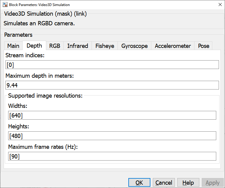
Stream indices (tunable offline)
The indices of the depth streams. The length of this vector determines the number of depth streams supported by the simulated device. The indices need not start at zero or one and need not be contiguous. If this parameter is empty then there will be no depth sensors for the simulated device.
Maximum depth in meters (tunable offline)
The maximum depth in meters for the depth camera. This value is used to provide the depth in meters when requested by a Video3D Capture block using the simulated card. The maximum pixel value of the input depth image is mapped to this maximum depth value. This parameter may be a vector or scalar. If it is empty then a maximum depth of one will be used. If it is shorter than the number of depth streams then the last element will be used for the remaining depth streams.
Widths (tunable offline)
The supported image resolution widths for depth streams. The image resolution and frame rate are HxW @ FPS where H, W and FPS are corresponding elements in the Widths, Heights and Maximum frame rates parameters.
Heights (tunable offline)
The supported image resolution heights for depth streams. The image resolution and frame rate are HxW @ FPS where H, W and FPS are corresponding elements in the Widths, Heights and Maximum frame rates parameters.
Maximum frame rates (tunable offline)
The supported maximum frame rates for each resolution for depth streams. The image resolution and frame rate are HxW @ FPS where H, W and FPS are corresponding elements in the Widths, Heights and Maximum frame rates parameters.
RGB Pane
The RGB pane of the dialog appears as follows:
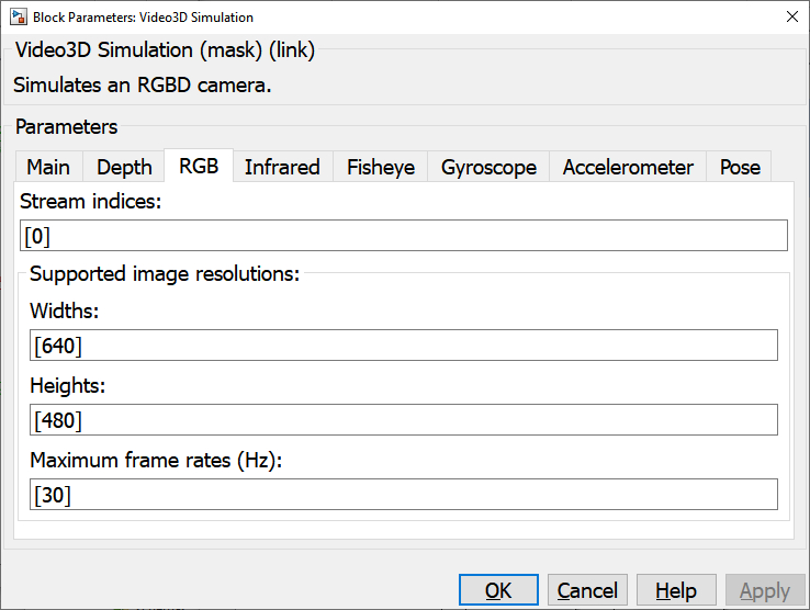
Stream indices (tunable offline)
The indices of the RGB streams. The length of this vector determines the number of RGB streams supported by the simulated device. The indices need not start at zero or one and need not be contiguous. If this parameter is empty then there will be no RGB sensors for the simulated device.
Widths (tunable offline)
The supported image resolution widths for RGB streams. The image resolution and frame rate are HxW @ FPS where H, W and FPS are corresponding elements in the Widths, Heights and Maximum frame rates parameters.
Heights (tunable offline)
The supported image resolution heights for RGB streams. The image resolution and frame rate are HxW @ FPS where H, W and FPS are corresponding elements in the Widths, Heights and Maximum frame rates parameters.
Maximum frame rates (tunable offline)
The supported maximum frame rates for each resolution for RGB streams. The image resolution and frame rate are HxW @ FPS where H, W and FPS are corresponding elements in the Widths, Heights and Maximum frame rates parameters.
Infrared Pane
The Infrared pane of the dialog appears as follows:
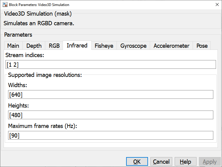
Stream indices (tunable offline)
The indices of the infrared streams. The length of this vector determines the number of infrared streams supported by the simulated device. The indices need not start at zero or one and need not be contiguous. If this parameter is empty then there will be no infrared sensors for the simulated device.
Widths (tunable offline)
The supported image resolution widths for infrared streams. The image resolution and frame rate are HxW @ FPS where H, W and FPS are corresponding elements in the Widths, Heights and Maximum frame rates parameters.
Heights (tunable offline)
The supported image resolution heights for infrared streams. The image resolution and frame rate are HxW @ FPS where H, W and FPS are corresponding elements in the Widths, Heights and Maximum frame rates parameters.
Maximum frame rates (tunable offline)
The supported maximum frame rates for each resolution for infrared streams. The image resolution and frame rate are HxW @ FPS where H, W and FPS are corresponding elements in the Widths, Heights and Maximum frame rates parameters.
Fisheye Pane
The Fisheye pane of the dialog appears as follows:
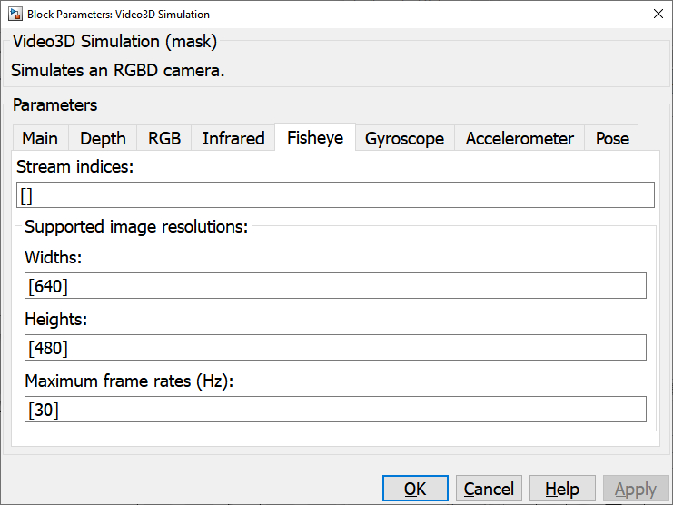
Stream indices (tunable offline)
The indices of the fisheye streams. The length of this vector determines the number of fisheye streams supported by the simulated device. The indices need not start at zero or one and need not be contiguous. If this parameter is empty then there will be no fisheye sensors for the simulated device.
Widths (tunable offline)
The supported image resolution widths for fisheye streams. The image resolution and frame rate are HxW @ FPS where H, W and FPS are corresponding elements in the Widths, Heights and Maximum frame rates parameters.
Heights (tunable offline)
The supported image resolution heights for fisheye streams. The image resolution and frame rate are HxW @ FPS where H, W and FPS are corresponding elements in the Widths, Heights and Maximum frame rates parameters.
Maximum frame rates (tunable offline)
The supported maximum frame rates for each resolution for fisheye streams. The image resolution and frame rate are HxW @ FPS where H, W and FPS are corresponding elements in the Widths, Heights and Maximum frame rates parameters.
Gyroscope Pane
The Gyroscope pane of the dialog appears as follows:
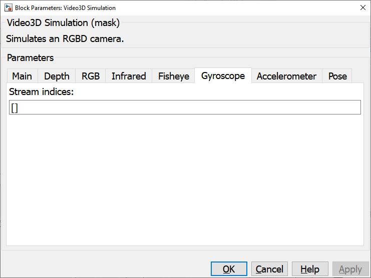
Stream indices (tunable offline)
The indices of the gyroscope streams. The length of this vector determines the number of gyroscope streams supported by the simulated device. The indices need not start at zero or one and need not be contiguous. If this parameter is empty then there will be no gyroscopes for the simulated device.
Accelerometer Pane
The Accelerometer pane of the dialog appears as follows:
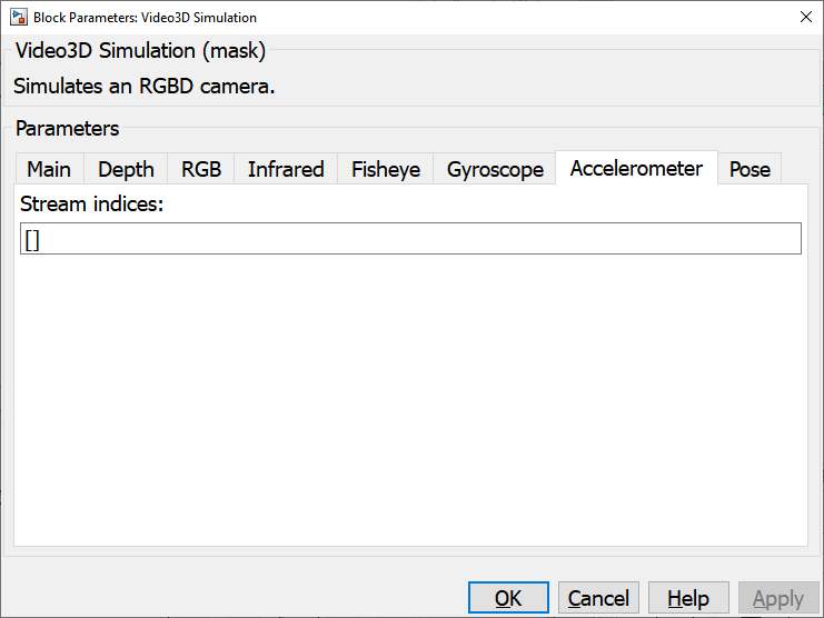
Stream indices (tunable offline)
The indices of the accelerometer streams. The length of this vector determines the number of accelerometer streams supported by the simulated device. The indices need not start at zero or one and need not be contiguous. If this parameter is empty then there will be no accelerometers for the simulated device.
Pose Pane
The Pose pane of the dialog appears as follows:
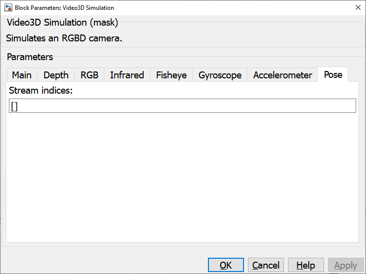
Stream indices (tunable offline)
The indices of the pose streams. The length of this vector determines the number of pose streams supported by the simulated device. The indices need not start at zero or one and need not be contiguous. If this parameter is empty then there will be no pose sensors for the simulated device.
Targets
|
Target Name |
Compatible* |
Model Referencing |
Comments |
|---|---|---|---|
|
Yes |
Yes |
||
|
Yes |
Yes |
||
|
Yes |
Yes |
||
|
Yes |
Yes |
||
|
Yes |
Yes |
||
|
Yes |
Yes |
||
|
Yes |
Yes |
||
|
Yes |
Yes |
||
|
Yes |
Yes |
||
|
Yes |
Yes |
||
|
Yes |
Yes |
||
|
Yes |
Yes |
||
|
Yes |
Yes |
||
|
Yes |
Yes |
Last fully supported in QUARC 2018. |
|
|
Rapid Simulation (RSIM) Target |
Yes |
Yes |
|
|
S-Function Target |
No |
N/A |
Old technology. Use model referencing instead. |
|
Normal simulation |
Yes |
Yes |
See Also
Copyright ©2026 Quanser Inc. This page was generated 2026-05-13. Submit feedback to Quanser about this page.
Link to this page.