
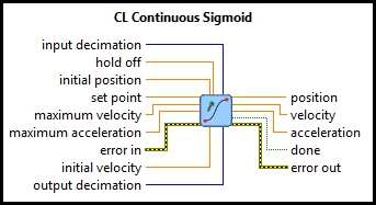
CL Continuous Sigmoid
| Owning Palette: | Sources |
| Requirements: | Quanser Rapid Control Prototyping Toolkit, LabVIEW 2022 or newer, Control Design and Simulation Module |
Description
Generates a sigmoid trajectory from the current position (and velocity) to the target position. Position, velocity and acceleration profiles are generated, as well as a signal to indicate when the trajectory has reached the target. Trajectories are recomputed whenever the target position changes.
Recommended Inputs or Dialog Box Options  Recommended inputs need not to be wired. They may be selected to appear as terminals or dialog parameters, but show up as terminals by default.
They appear in simple text in the context help window for the VI.
Recommended inputs need not to be wired. They may be selected to appear as terminals or dialog parameters, but show up as terminals by default.
They appear in simple text in the context help window for the VI.

|
set point is the current target position for the trajectory. If this input changes then the trajectory is re-computed. The input is sampled at the sampling rate specified by the input sample time parameter. |
|
|
maximum velocity provides the maximum velocity that will be allowed in the trajectory. The output trajectory will never exceed the specified maximum velocity. |
|
|
maximum acceleration provides the maximum acceleration that will be produced in the trajectory. The output trajectory will never exceed the specified maximum acceleration. |

|
error in describes error conditions occurring before the VI executes. If an error has already occurred, the VI returns the value of the error in cluster in error out.
|


Optional Inputs or Dialog Box Options
Optional inputs need not to be wired. They may appear as terminals or dialog parameters, but show up as dialog parameters by default.
They are indicated but not labelled in the context help window for the VI.

|
input decimation defines the decimation of the set point input. The set point input is sampled every n-th sampling instant, where n is the input decimation value. In other words, the input decimation is multiplied by the sample time of the CD&Sim Loop to yield the sample time of the set point input. |
|
|
hold off is the time between the trajectory reaching its target and the done signal being asserted. The hold off should generally be equal to, or greater than, the output sample time. hold off is needed when the done signal is used to trigger other events. Suppose the first trajectory reaches its target and the done signal is asserted. If for the next trajectory the current position and target position are the same, the done signal never goes low if the hold off is zero because we are already at the target position. In an event-driven system, the fact that done never goes low means that it will not have a rising edge and will not produce another trigger event. By specifying a non-zero hold off, the done signal will always go low for at least the hold off. Hence, it will always produce a trigger event. |
|
|
initial position is used when the VI is started. Once the VI is started, the current position is always determined from the current trajectory. |
|
|
initial velocity is used when the VI is started. Once the VI is started, the current velocity is always determined from the current trajectory. |
|
|
output decimation defines the decimation of the position trajectory, as well as the velocity and acceleration outputs. The sample time of the outputs is the output decimation multiplied by the sample time of the CD&Sim Loop. |
Outputs

|
position is the position profile. It is a smooth trajectory going from the initial position to the target position. |
||||||
|
|
velocity is the velocity profile. It is a continuous curve going from the initial velocity to zero. The velocity is computed independently of the position - it is not computed via a numerical derivative of the position. |
||||||
|
|
acceleration is the acceleration profile. Due to the nature of the sigmoid trajectory, the acceleration curve is discontinuous. Like the velocity, it is also computed independently of the position rather than by numerical differentiation. |
||||||
|
|
done is a signal indicating when the trajectory is complete. The signal is zero until the set point is reached. After reaching the target position, the VI waits for the number of seconds specified in the hold off parameter before setting the done signal to one. |
||||||

|
error out contains error information. If the error in cluster indicated an error, the error out cluster contains the same information. Otherwise, error out describes the error status of this VI.
|


Details
CL Continuous Sigmoid generates a smooth trajectory from the initial position and initial velocity to the set point. The velocity at the target position will be zero. It uses the specified maximum velocity and acceleration to derive the fastest possible trajectory from the initial position to the set point.
The CL Continuous Sigmoid vi samples its inputs at regular intervals, determined by the input sample time parameter. Each time the inputs are sampled, the trajectory is re-computed. Hence, the sample time should normally be slower than the time taken to traverse the trajectory.
The output of the CL Continuous Sigmoid is generated using the sampling rate specified by the output sample time parameter, which may be set to zero for a continuous-time trajectory.
The CL Continuous Sigmoid provides the done signal to indicate when the trajectory reaches its target. A hold off time can also be specified to wait a certain amount of time after reaching the target before asserting the done signal. This output may be used to trigger another event, or reset encoder counts, for example.
Feedthrough Behaviour
All input/output pairs of this function have direct feedthrough behaviour.
Examples
| RCP CL Continuous Sigmoid Example | This example demonstrates the use of RCP CL Continuous Sigmoid, which generates a sigmoid trajectory from the current position (and velocity) to the target position. |
See Also
| CL Smooth Signal Generator | Outputs a waveform whose amplitude and frequency may be changed without causing a discontinuity in the output and may be driven by inputs to the vi. |
Targets
|
Target |
Supported |
Comments |
|---|---|---|
|
Yes |
Fully supported. |
Copyright © Quanser Inc. This page was generated 2024-11-15. Submit feedback to Quanser about this page.
Link to this page.