
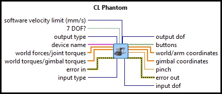
CL Phantom
| Owning Palette: | Devices/3DSystems |
| Requirements: | Quanser Rapid Control Prototyping Toolkit, LabVIEW 2022 or newer, Control Design and Simulation Module, Phantom Device Drivers (Currently Geomagic Touch Device Driver) and OpenHaptics Toolkit |
Description
CL Phantom can be used to control the family of Phantom haptic devices. All these devices have 6 DoF outputs (encoders) to read, and 3 or 6-DOF inputs (actuators) to control.
Installation Requirements
 In order to use the CL Phantom, the "Phantom Device Drivers" version 4.2.131 or later (e.g., Geomagic Touch Device Driver version 2014.2)
and "OpenHaptics Toolkit" version 3.0 (released on Jan. 2009) or later must be installed. Also, before using CL Phantom for the first time,
the installation directory of the OpenHaptics Toolkit (e.g. C:\Program Files\SensAble\3DTouch) must be added to the system path environment variable.
It will be necessary to restart LabVIEW after setting the environment variable because applications make a local copy of the environment variables at startup.
Besides, the current 3D System Geomagic Touch Device is using a USB to Ethernet converter and the driver for it (included in the CD in the device package)
need to be installed.
In order to use the CL Phantom, the "Phantom Device Drivers" version 4.2.131 or later (e.g., Geomagic Touch Device Driver version 2014.2)
and "OpenHaptics Toolkit" version 3.0 (released on Jan. 2009) or later must be installed. Also, before using CL Phantom for the first time,
the installation directory of the OpenHaptics Toolkit (e.g. C:\Program Files\SensAble\3DTouch) must be added to the system path environment variable.
It will be necessary to restart LabVIEW after setting the environment variable because applications make a local copy of the environment variables at startup.
Besides, the current 3D System Geomagic Touch Device is using a USB to Ethernet converter and the driver for it (included in the CD in the device package)
need to be installed.
When using an academic version of the OpenHaptics software, no licensing is required from Sensable to run the model. However, in the case of using an industrial version of the OpenHaptics Toolkit, a license file is required to get access to the API functions used by CL Phantom It is recommended that the license file is placed in a local directory (eg. C:\OpenHaptics License). Then, an environment variable named "OH_SDK_LICENSE_PATH" should be set with its value as the location of the license file.
As an alternative, the license file can be placed in the same folder as the OpenHaptics program's executable file (the model directory).
Please run the "PHANTOM Test" program from the "Phantom Device Drivers" to calibrate the device for better performance. In the current version, "Geomagic Touch Setup" and "Geomagic Touch Diagnostic" from "Geomagic Touch Device Drivers" needs to be run instead.
Recommended Inputs or Dialog Box Options  Recommended inputs need not to be wired. They may be selected to appear as terminals or dialog parameters, but show up as terminals by default.
They appear in simple text in the context help window for the VI.
Recommended inputs need not to be wired. They may be selected to appear as terminals or dialog parameters, but show up as terminals by default.
They appear in simple text in the context help window for the VI.

|
world forces/arm torques is a 3-element array containing the forces or torques to send to the base, shoulder and elbow joints of the Phantom device. The input type determines whether the world forces/arm torques input is interpreted as forces or torques. If the input type is Cartesian space then the world forces/arm torques input is a vector of force in Cartesian world coordinates. The units are N. Facing the device, toward the user is the positive x-axis, right is the positive y-axis and up is the positive z-axis. The order of the elements is X, Y and Z. If the input type is Joint space then the world forces/arm torques input is a vector of torques in mN-m to apply to the base, shoulder and elbow joints respectively. |
|
|
world torques/gimbal torques is a 3-element array containing the torques to apply to the gimbal of the Phantom device. For Phantom devices with only three actuated degrees-of-freedom this input is ignored. The units are mN-m. The order of the elements is yaw, pitch and roll. The input type determines the coordinate space in which these torques are interpreted. If the input type is Cartesian space then the world torques/gimbal torques input is a vector of torques in Cartesian world coordinates. If the input type is Joint space then the world torques/gimbal torques input is a vector of torques to apply to the gimbal joints. |

|
error in describes error conditions occurring before the VI executes. If an error has already occurred, the VI returns the value of the error in cluster in error out.
|
Optional Inputs or Dialog Box Options
Optional inputs need not to be wired. They may appear as terminals or dialog parameters, but show up as dialog parameters by default.
They are indicated but not labelled in the context help window for the VI.

|
software velocity limit is an option that can be activated to limit the Cartesian velocity of the device arm for safety features. User can limit the velocity by setting the software velocity limit value to a positive number, and disable this feature by setting a negative number. However, be extra careful when setting this value to zero as undesired behaviour may result. The units are mm/s. |

|
7-DOF? is true when the 7-DOF end effector is available on the device (thumb-pad or scissors), checking this option enables the user to read the pinch value from the end effector. |

|
output type determines the coordinates output from the world/arm coordinates and gimbal coordinates outputs. Three coordinate spaces are available: Encoder values, Position and gimbal angles, and Joint and gimbal angles. When Encoder values is selected, the outputs are raw encoder counter values. When Position and gimbal angles is chosen, the world/arm coordinates are Cartesian world coordinates of the end-effector in metres and the gimbal coordinates are gimbal joint angles in radians. The Joint and gimbal angles option produces joint angles in radians at the world/arm coordinates output and gimbal joint angles in radians at the gimbal coordinates output. |

|
device name is the name assigned to the device. The device has to be configured with Phantom Configuration (e.g., Geomagic Touch Setup) program with the same name (e.g., "Default Device"), so the model will access the correct device. |
|
|
input type determines the coordinates of the inputs. Two coordinate spaces are available: Cartesian space and Joint space. When Cartesian space is selected, the world forces/arm torques input is the forces in N to apply to the end-effector in Cartesian world coordinates. The world/gimbal torques input is the torques to apply to the end-effector in mN-m. Not all Phantom devices have actuated gimbal joints. When Joint space is chosen, the world forces/arm torques input is the torques in mN-m to apply to the base, shoulder and elbow joints of the device. The world/gimbal torques input is the torques in mN-m to apply to the gimbal joints. Not all Phantom devices have actuated gimbal joints. |
Outputs

|
output dof is the actual number of degrees-of-freedom output from the device. In other words, it includes both actuated and non-actuated joints. |
||||||

|
buttons is the state of the buttons on the device. A value of true means the button is depressed. False means it is released. |
||||||

|
The value of the world/arm coordinates output is a 3-vector whose coordinate system depends on the output type. When the output type is Encoder values then the world/arm coordinates output is raw encoder counter values for the base, shoulder and elbow joints. When the output type is Position and gimbal angles, the world/arm coordinates output is the Cartesian world coordinates of the end-effector in metres. Facing the device, toward the user is the positive x-axis, right is the positive y-axis and up is the positive z-axis. The units are metres. The order of the elements is X, Y and Z. When the output type is Joint and gimbal angles, the world/arm coordinates output is the joint angles of the base, shoulder and elbow joints respectively in radians. |
||||||
|
|
The value of the gimbal coordinates output is a 3-vector whose coordinate system depends on the output type. When the output type is Encoder values then the gimbal coordinates output is raw encoder counter values for the gimbal joints. Otherwise the gimbal coordinates output is the angles of the gimbal joints in radians. The order of the elements is yaw, pitch and roll. |
||||||

|
The pinch output is only valid for 7-DOF devices. It is only enabled when the 7 DOF? input is true. It represents the pinch value of the thumb-pad or scissors as a normalized encoder value. |
||||||
|
|
input dof is the actual number of degrees-of-freedom for input to the device. In other words, it is the number of actuated joints. |
||||||

|
error out contains error information. If the error in cluster indicated an error, the error out cluster contains the same information. Otherwise, error out describes the error status of this VI.
|


Details
CL Phantom can be used to control the family of Phantom haptic devices. All these devices have 6 degree-of-freedom (DOF) outputs (encoders) to read, and 3 or 6-DOF inputs (actuators) to control. The Phantom VI can send commands in two different coordinate spaces to the Phantom device: Cartesian Space and Joint Space. When working in Cartesian mode, the VI sends Cartesian forces to the robot. If the device is 6-DOF then roll, pitch, and yaw torque commands are also sent to the device gimbal. In Joint space mode, torques are sent to the actuators of the device separately: three values for the base, shoulder and elbow joints and an additional three values for the gimbal joints if the device is 6-DOF.
Also, depending on the user's choice, the VI can output the encoder values, position of the device arm, or joint and gimbal angles of the device. Moreover, the button states and the optional 7-DOF attachment (thumb-pad or scissors) are read through this VI.
The units for position measurements are metres and the units for angular measurements are radians. Forces are in Newtons and torques are in mN-m.
Feedthrough Behaviour
All input/output pairs of this function have direct feedthrough behaviour.
Examples
| RCP CL Phantom Example | This example demonstrates how to use the CL Phantom VI to control the family of Phantom haptic devices. |
Targets
|
Target |
Supported |
Comments |
|---|---|---|
|
Yes |
Fully supported. |
Copyright © Quanser Inc. This page was generated 2024-11-15. Submit feedback to Quanser about this page.
Link to this page.