
Inverse Modulus
| Owning Palette: | Utilities |
| Requirements: | Quanser Rapid Control Prototyping Toolkit, LabVIEW 2022 or newer |
Description
The Inverse Modulus VI computes the accumulated output for signals which wrap, such as multi-turn potentiometer measurements.
Recommended Inputs  Recommended inputs need not be wired. They appear as simple text in the context help window for the VI.

|
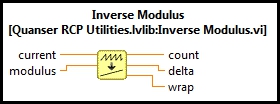
current is the input signal that wraps. |
|
|
modulus is the modulus upon which the input signal is based and determines the range of values over which the input is expected to wrap. Refer to the Details section for an important detailed description of this terminal. |
Outputs

|
count is an "unwrapped" version of the input signal. |
|
|
delta is the change in the input since the last iteration, accounting for wrapping. Divide by the time elapsed since the last iteration to get the velocity of the input signal. |
|
|
wrap is the number of times the input signal wrapped. The sign of this value indicates the direction it wrapped. |
Details
The Inverse Modulus VI computes the accumulated output for signals which wrap. For example, a potentiometer may output a voltage in the range 0V to 5V for each revolution of the potentiometer shaft. Hence, there's a point in the revolution of the potentiometer in which the voltage jumps from 5V to 0V or vice versa. Such discontinuities can be a problem for control algorithms. Furthermore, the number of revolutions turned is lost. This VI provides a solution by detecting these discontinuities and adjusting the output to reflect the number of revolutions that have occurred. In the above example, the output of the Inverse Modulus VI would not jump from 5V to 0V but would instead continue to increase beyond 5V. Likewise, when moving in the opposite direction, the output would not jump from 0V to 5V but would go negative.
A similar situation occurs when using the velocity of the signal which wraps. In the same example, if the potentiometer were used in a velocity or PD control application the velocity would jump whenever the output voltage wrapped between 0V and 5V. The Inverse Modulus VI has a delta output that computes the change in the input signal in a way that eliminates this discontinuity in the derivative of the input signal.
The only constraint upon this VI is that it must be executed frequently enough that the input does not change by more than half the modulus between executions. In other words, the sampling rate of the model must be more than twice the frequency of the input signal - the standard Nyquist criterion.
The modulus refers to the modulus in modulo arithmetic, since an input signal which wraps is congruent to the unwrapped output. Mathematically, the Inverse Modulus VI computes the count output such that the following relationship is satisfied:
current = (count - c) (mod modulus) + c
where c is the minimum possible value of the current input signal. The constant, c, allows for signed or unsigned input signals, or even arbitrary offsets. It is deduced by the VI and does not need to be entered.
For example, consider an encoder with an 8-bit unsigned counter. Hence, the counter values may vary between 0 and 255. If the encoder rotates in the positive direction beyond a count of 255 then the count wraps immediately back to 0 and continues counting upward. Likewise, if the encoder rotates in the negative direction beyond a count of 0 then the count wraps immediately back to 255 and continues counting downward. If we had a signed counter of infinite range then it would never wrap. Let's call this the "unwrapped" count. Consider the values of the two counters when the shaft is rotating in the positive direction at 100 counts per sampling instant. The values are also shown in hexadecimal in parentheses because wrapping is equivalent to discarding all but the two least significant hexadecimal digits for an 8-bit counter.
|
8-bit Unsigned Counter |
Unwrapped Count |
Comment |
|---|---|---|
|
0 (0x0) |
0 (0x0) |
Both counters start at 0. |
|
100 (0x64) |
100 (0x64) |
|
|
200 (0xC8) |
200 (0xC8) |
|
|
44 (0x2C) |
300 (0x12C) |
At this point, the 8-bit unsigned counter wraps. Its value becomes 300 (mod 256) = 44. |
|
144 (0x90) |
400 (0x190) |
|
|
244 (0xF4) |
500 (0x1F4) |
|
|
88 (0x58) |
600 (0x258) |
At this point, the 8-bit unsigned counter wraps again. Its value becomes 600 (mod 256) = 88. |
|
188 (0xBC) |
700 (0x2BC) |
And so it continues... |
The Inverse Modulus VI calculates the unwrapped count in this table (the second column) given the values in the first column over time. Notice that the 8-bit values in the first column can be calculated from the unwrapped count in the second column using the modulo operation:
8-bit unsigned counter = unwrapped count (mod 256)
or in terms of the terminals of this VI:
current = count (mod modulus)
where the modulus input is 256.
Note that the Inverse Modulus VI handles signed input signals as well. Consider the same example, but this time let the encoder counter be a signed 8-bit counter. A signed 8-bit value ranges from -128 to +127. Hence, in this case, the sequence of count values will be:
|
8-bit Signed Counter |
Unwrapped Count |
Comment |
|---|---|---|
|
0 (0x0) |
0 (0x0) |
Both counters start at 0. |
|
100 (0x64) |
100 (0x64) |
|
|
-56 (0xC8) |
200 (0xC8) |
At this point, the 8-bit signed counter wraps. Its value becomes (200 + 128) (mod 256) - 128 = -56. |
|
44 (0x2C) |
300 (0x12C) |
|
|
-112 (0x90) |
400 (0x190) |
At this point, the 8-bit signed counter wraps again. Its value becomes (400 + 128) (mod 256) - 128 = -112. |
|
-12 (0xF4) |
500 (0x1F4) |
|
|
88 (0x58) |
600 (0x258) |
|
|
-68 (0xBC) |
700 (0x2BC) |
At this point, the 8-bit signed counter wraps again. Its value becomes (600 + 128) (mod 256) - 128 = -68. |
As before, the Inverse Modulus VI calculates the unwrapped count in this table (the second column) given the values in the first column over time. Notice that the 8-bit values in the first column can be calculated from the unwrapped count in the second column using the modulo operation:
8-bit signed counter = (unwrapped count + 128) (mod 256) - 128
or in terms of the terminals of this VI:
current = (count - c) (mod modulus) + c
where the modulus input is 256 and the constant, c, is -128, the minimum possible value of the 8-bit signed encoder counter. Note that the Inverse Modulus VI can calculate the unwrapped count without knowing the value of c.
Observe that for the 8-bit unsigned and 8-bit signed examples, the modulus is 256 in both cases.
| In general, given an n-bit encoder counter, the modulus should be set to 2 n . For the 8-bit encoder examples, n=8 so the modulus is 28 = 256. |

The Inverse Modulus VI is not limited to integer-valued input signals. For example, consider a multi-turn potentiometer whose voltage ranges from 0.0V to 5.0V and wraps with each revolution. Because the signal wraps regardless of the sensor technology used to measure the voltage, the modulus should be set to the voltage range of 5. The resolution of the A/D converter used to measure the voltage is irrelevant in this case.
The same formula:
current = (count - c) (mod modulus) + c
applies but the modulo operation is real-valued in this case. The following table shows the 5V potentiometer example with the voltage changing by 1.3V every sampling instant:
|
Measured Voltage |
Unwrapped Voltage |
Comment |
|---|---|---|
|
0 |
0 |
Both voltages start at 0. |
|
1.3 |
1.3 |
|
|
2.6 |
2.6 |
|
|
3.9 |
3.9 |
|
|
0.2 |
5.2 |
The measured voltage wraps and may be computed as 5.2 (mod 5.0) = 0.2 |
|
1.5 |
6.5 |
And so it continues... |
| When deciding on the appropriate modulus, be sure to account for the source of the wrapping. In the multi-turn potentiometer example, the potentiometer voltage will wrap independent of the sensor used to measure the voltage. Hence, the modulus should be determined by the voltages at which the potentiometer wraps, not the resolution of the A/D used to measure it. However, a 24-bit encoder will wrap because of the limited bit width of the encoder counter itself. Hence, the modulus should be determined by the bit width of the encoder counter and is generally 2 n where n is the number of bits in the encoder counter. |
Note that the modulus input is not restricted to integer values. For example, a multi-turn potentiometer might produce a voltage ranging from 0.0V to 1.25V, in which case a modulus of 1.25 is appropriate.
The following table gives general guidelines for choosing the appropriate modulus to get the desired results.
|
Scenario |
Modulus |
|---|---|
|
Multi-turn potentiometer |
Set the modulus to the peak-to-peak voltage range of the potentiometer. For example, if the potentiometer varies from -2.5V to +2.5V, or from 0V to 5V, set the modulus to 5.0 in both cases. |
|
Encoder counter |
Set the modulus to 2 n where n is the number of bits in the encoder counter. |
|
Integer-valued input |
For a general integer-valued input ranging from MIN to MAX inclusive (i.e. both MIN and MAX are valid values), set the modulus to (MAX - MIN + 1). For example, for an integer-valued input ranging from -100 to +100 inclusive, set the modulus to 201 (not 200!). Note that the n-bit encoder is a special case, as the minimum and maximum values of an n-bit signed counter are MIN=-2 (n-1) and MAX=2 (n-1) - 1 so (MAX - MIN + 1) = 2 n . |
|
Scaled encoder counter |
Suppose an n-bit encoder count is converted to radians by multiplying by a real-valued scale factor, S, and then this scaled result is passed to the Inverse Modulus VI. In this case, set the modulus to S*2 n . |
|
Scaled integer-valued input |
For a general integer-valued signal ranging from MIN to MAX inclusive (i.e. both MIN and MAX are valid values) that has been multiplied by a scale factor, S, prior to feeding it to the current input of the Inverse Modulus VI, set the modulus to S*(MAX - MIN + 1). |
Feedthrough Behaviour
All input/output pairs of this function have direct feedthrough behaviour.
Examples
| RCP Inverse Modulus Example |
Targets
|
Target |
Supported |
Comments |
|---|---|---|
|
Yes |
Fully supported. |
Copyright © Quanser Inc. This page was generated 2024-11-15. Submit feedback to Quanser about this page.
Link to this page.