
RCP Inverse Modulus Example
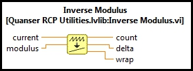
This example demonstrates how to use the RCP Inverse Modulus VI. For a detailed description of this VI and how it operates, please refer to the RCP Inverse Modulus help page.
System Requirements
Please refer to the Rapid Control Prototyping (RCP) Toolkit System Requirements to run this example. This example does not require any other hardware.
Configuring the Example
There is no configuration required to run this VI on a Windows PC. Once the RCP Inverse Modulus Example.lvproj is open,
click the RCP Inverse Modulus Example.vi under My Computer and you are ready
to execute the example.
Running the Example
Click on the VI button or select from the menu to start the VI.
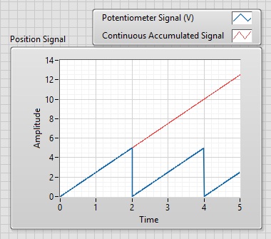
In this example, a potentiometer outputs a voltage in the range 5V to 0V for each revolution
of the potentiometer shaft, with a voltage discontinuity at each turn. Such discontinuities
are a problem for control algorithms. In the Position Signal Chart, examine how
the Inverse Modulus VI accumulated output signal (in red) is computed from the wrapping
potentiometer signal (in blue) in order to provide a continuous position signal, which is
directly usable in feedback control systems.
Click on the Front Panel button to stop the VI.
Copyright © Quanser Inc. This page was generated 2024-11-15. Submit feedback to Quanser about this page.
Link to this page.