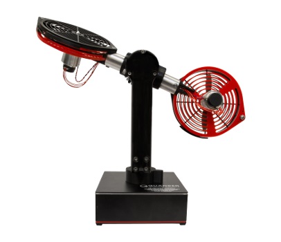

Quanser Aero-USB
The Quanser Aero-USB is an integrated lab experiment. It is designed to help teach fundamental control concepts and theories on an easy-to-use and intuitive platform. The Quanser Aero-USB is also suitable for advanced aerospace research applications. For more information, visit the Quanser website for the Quanser Aero-USB.
The RCP Toolkit driver name for this card is quanser_aero_usb.

The features of the Quanser Aero-USB are:
The Quanser Aero-USB I/O channels are described below.
Clocks
There are currently no configuration options for the Quanser Aero-USB clocks.
Analog Inputs
The Quanser Aero-USB supports two analog inputs. The analog inputs measure the current to each motor in Amperes. Their maximum range is ±3A. Channel 0 is the current sense for motor 0 and channel 1 is the current sense for motor 1.
Analog Outputs
The Quanser Aero-USB supports two analog outputs. The analog outputs drive the motor voltages. Their maximum range is ±24V. Channel 0 drives motor 0 and channel 1 drives motor 1.
In order to have analog outputs set to a particular voltage when the block diagram is run or stopped, the analog outputs must be configured on the HIL Initialize VI's Analog Outputs tab.
Once the analog output ranges have been configured, set the Initial analog outputs and Final analog outputs to the desired voltages.
Digital Inputs
The Quanser Aero-USB supports seven digital inputs, which are used for diagnostics. The digital inputs are enumerated in the table below.
|
Channel |
Description |
|---|---|
|
0 |
Amplifier 0 fault. |
|
1 |
Amplifier 1 fault. |
|
2 |
Motor 0 stall detected. |
|
3 |
Motor 0 stall error. |
|
4 |
Motor 1 stall detected. |
|
5 |
Motor 1 stall error. |
|
6 |
Packet checksum error. |
Digital Outputs
The Quanser Aero-USB supports two digital outputs. The digital outputs act as enables for the motor drive circuitry. Channel 0 enables motor 0 and channel 1 enables motor 1. When the output is low, the corresponding motor is disabled. When the output is high, the corresponding motor amplifier is enabled.
Encoder Inputs
The Quanser Aero-USB supports four encoder inputs. Each channels provide a 24-bit count value. All channels only support 4X quadrature mode.
In order to set the encoder counters to a particular count when the model is loaded, the encoder inputs must be configured on the HIL Initialize VI's Encoder Inputs tab.
PWM Outputs
The Quanser Aero-USB card does not support PWM outputs.
Other Inputs
The Quanser Aero-USB card does not support other inputs.
Other Outputs
The Quanser Aero-USB supports three other output channels, allowing the color of the LED panel to be controlled. Note that each channel supports fractional values between 0 and 1, allowing full RGB color. Refer to the table below for a list of the channels:
|
Channel |
Description |
Range |
|---|---|---|
|
11000 |
Red component for LED color |
0 to 1 |
|
11001 |
Green component for LED color |
0 to 1 |
|
11002 |
Blue component for LED color |
0 to 1 |
Interrupts
The Quanser Aero-USB card, or its driver, does not support any interrupt sources.
Watchdog
The Quanser Aero-USB supports a watchdog timer for resetting the outputs on watchdog expiry. Namely, the analog, digital and other output channels will be reset to the user-defined values on watchdog expiry. Resetting of the outputs occurs without software intervention, and therefore may be used as a safety mechanism in the event of software failure.
To enable the resetting of the analog or digital, check the Set output on watchdog options on the respective tabs of the HIL Initialize VI parameters dialog. Set the Output on watchdog expiry fields to the desired values. Then place a CL HIL Watchdog VI in the diagram.
Once the watchdog has expired, further output is disabled until the watchdog state is cleared. Hence, in RCP, the outputs will remain in the watchdog state even after the VI is stopped, unless a CL HIL Watchdog Clear VI is used to clear the watchdog state. Restarting the VI will automatically clear the watchdog.
Board-Specific Options
The Quanser Aero-USB card does not support any board-specific options.
Properties
The Quanser Aero-USB driver currently supports the following read-only properties:
|
Property |
Type |
Description |
|---|---|---|
|
PROPERTY_INTEGER_VENDOR_ID |
Integer |
Vendor identifier associated with the hardware |
|
PROPERTY_INTEGER_PRODUCT_ID |
Integer |
Product identifier associated with the hardware |
|
PROPERTY_INTEGER_FIRMWARE_MAJOR_VERSION |
Integer |
Major version number of the firmware (hardware) |
|
PROPERTY_INTEGER_FIRMWARE_MINOR_VERSION |
Integer |
Minor version number of the firmware (Qube interface) |
|
PROPERTY_INTEGER_FIRMWARE_BUILD |
Integer |
Build number of the firmware (currently always zero) |
|
PROPERTY_INTEGER_FIRMWARE_REVISION |
Integer |
Revision number of the firmware (currently always zero) |
|
PROPERTY_STRING_MANUFACTURER |
String |
Manufacturer of the device |
|
PROPERTY_STRING_PRODUCT_NAME |
String |
Product name of the device |
|
PROPERTY_STRING_MODEL_NAME |
String |
Model name of the device |
|
PROPERTY_STRING_SERIAL_NUMBER |
String |
Serial number of the device |
|
PROPERTY_STRING_FIRMWARE_VERSION |
String |
Firmware version of the PC interface |
Targets
|
Target |
Supported |
Comments |
|---|---|---|
|
Yes |
Fully supported. |
See Also

Copyright © Quanser Inc. This page was generated 2021-09-24. Submit feedback to Quanser about this page.
Link to this page.