
HIL Initialize
| Owning Palette: | HIL |
| Requirements: | Quanser Rapid Control Prototyping Toolkit, LabVIEW 2022 or newer |
Description
Initializes a hardware-in-the-loop (HIL) card for use with the other HIL VIs or CL HIL Control & Simulation Loop VIs.
Dialog Box Options
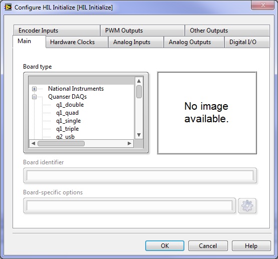
The HIL Initialize VI has an extensive set of configuration parameters. Double-click on the VI to open the configuration dialog shown below.
The configuration dialog is divided into tabs to make it easier to use. There are eight tabs:
- Main
- Hardware Clocks
- Analog Inputs
- Analog Outputs
- Digital I/O
- Encoder Inputs
- PWM Outputs
- Other Outputs
The purpose of each tab is to readily configure the particular type of I/O for the card in one place. For example, the directions of programmable digital I/O lines may be set, as well as the initial and final values for outputs. The options available on each tab are described in more detail below, in the corresponding section.
Main Tab
Choosing a Board
Choose a board type from the treeview containing a list of the supported cards. Selecting a board will configure all the other fields in the configuration dialog to default values. Pick the card you intend to use for the current diagram. It is possible to change boards later just by selecting a new board type, but remember that all the other fields will be reset to default values whenever you change boards.
The picture below shows the Main tab of the HIL Initialize configuration dialog when the q8_usb has been selected.
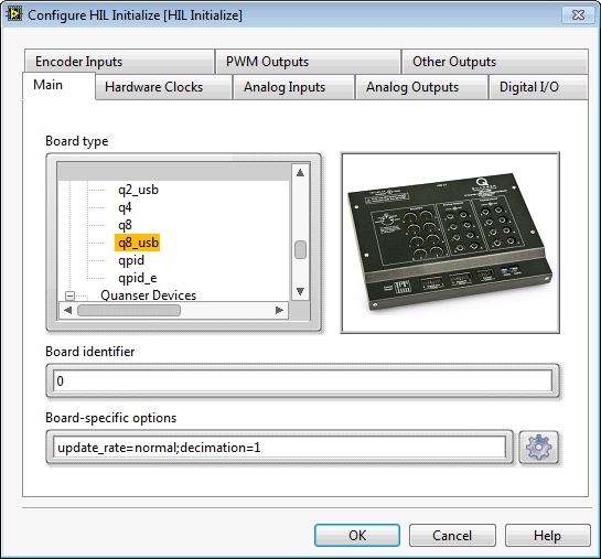
Notice that the board identifier and board-specific options are automatically initialized when the q8_usb board type is chosen.
Board Identifier
The board identifier is used to distinguish between multiple cards of the same type in the system. For example, if two QPIDe cards are installed in the computer then the board identifier is used to differentiate between the two boards. The board identifier is typically a number, with the first board of a particular type being board "0" and subsequent boards numbered sequentially thereafter. For cards made by National Instruments, the identifier set up in Measurement and Automation Explorer (MAX) may also be used.
Board-Specific Options
The board-specific options field is a string represent options that are very specific to the card and are generally not available on other boards. The format of the field is always:
option1=value1;option2=value2;...
with no spaces in between. Put double quotes around a value if the value contains spaces. Refer to the documentation for the card for a list of the options available.
| If the settings button beside the board-specific options field is enabled then pressing it will open a custom dialog for changing these options. |

Hardware Clocks
The Hardware Clocks tab is used to configure any hardware timebases on the card. Most Quanser cards have at least one hardware timebase, which may be multipurpose. The Hardware Clocks tab is illustrated below:
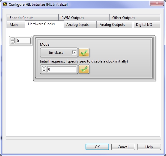
The array indexer is used to select the clock. Clocks are numbered from 0 to N-1, where N is the number of clocks. Different settings may be applied for each hardware clock.
Mode
In general, a clock may be configured in one of three modes:
- timebase mode
- PWM output mode
- encoder input mode
The timebase mode is the standard mode. In timebase mode the clock acts like a hardware timebase for the diagram when one of the CL HIL Timebase VIs is placed in the Control Design & Simulation loop. Hardware timebases generally allow faster clock rates and/or finer granularity in the sampling period to be achieved.
The PWM output mode is provided for those cards that allow hardware clocks to be used as a timebase or a PWM output. Quanser's Q8-PCI card is an example of a card that allows its clocks to be used as optional PWM outputs. A clock configured as a PWM output cannot be used as a timebase at the same time.
The encoder input mode is provided for those cards that allow hardware clocks to be used as a timebase or encoder input. Sensoray's Model 626 card is an example of a card that allows its clocks to be used as optional encoder inputs. A clock configured as an encoder input cannot be used as a timebase at the same time.
| If the button next to the Mode field is checked, then the clock mode of the clock is programmed when the HIL Initialize VI executes. If the button is not checked, but shows a red X, then the clock mode is not programmed but is left at its current value. |

Initial frequency
On some cards, the initial frequency of the clock may be set. This feature can be useful if the clock output is available on an external pin or the clock is being used as an interrupt source rather than a timebase.
| If the button next to the Initial frequency field is checked, then the clock frequency of the clock is programmed when the HIL Initialize VI executes. If the button is not checked, but shows a red X, then the clock frequency is not programmed but is left at its current value. |
Analog Inputs
The Analog Inputs tab is used to configure the analog inputs of the card. Only the analog input range may currently be configured, by setting the maximum and minimum values of the range of each channel. The Analog Inputs tab is depicted below:
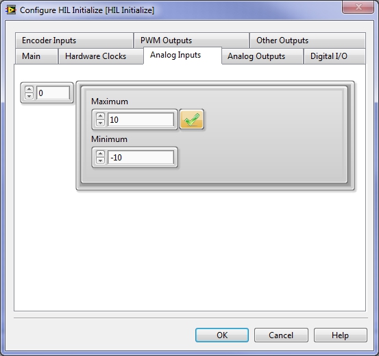
Maximum
The maximum field indicates the maximum value of the analog input range. Cards typically only support specific ranges, so the value is not arbitrary. The tooltip for the field should provide information on what analog input ranges are acceptable.
Minimum
The minimum field indicates the minimum value of the analog input range. For unipolar ranges, this value is zero. Cards typically only support specific ranges, so the value is not arbitrary. The tooltip for the field should provide information on what analog input ranges are acceptable.
| If the button next to the Maximum field is checked, then the analog input range for this channel is programmed when the HIL Initialize VI executes. If the button is not checked, but shows a red X, then the analog input range for this channel is not programmed but is left at its current value. |
Analog Outputs
The Analog Outputs tab is used to configure the analog outputs of the card. Not only may the analog output range be set, but the initial and final values of the analog outputs may be specified, as well as the value to assign if a watchdog timer expires. The Analog Outputs tab is depicted below:
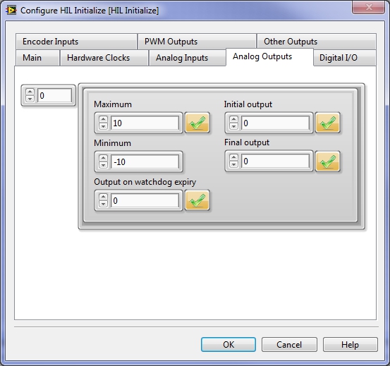
Maximum
The maximum field indicates the maximum value of the analog output range. Cards typically only support specific ranges, so the value is not arbitrary. The tooltip for the field should provide information on what analog output ranges are acceptable.
Minimum
The minimum field indicates the minimum value of the analog output range. For unipolar ranges, this value is zero. Cards typically only support specific ranges, so the value is not arbitrary. The tooltip for the field should provide information on what analog output ranges are acceptable.
| If the button next to the Maximum field is checked, then the analog output range for this channel is programmed when the HIL Initialize VI executes. If the button is not checked, but shows a red X, then the analog output range for this channel is not programmed but is left at its current value. |
Output on watchdog expiry
If a watchdog timer is used, then the value of the Output on watchdog expiry field is written to the specified analog output channel if the watchdog expires. This capability is extremely important for ensuring the safety of the control system.
| If the button next to the Output on watchdog expiry field is checked, then the analog output channel is reset to the given value if the watchdog timer expires. If the button is not checked, but shows a red X, then the analog output channel is not programmed if the watchdog expires but is left at its current value. |
Initial output
The value of this field is written to the analog output channel when the HIL Initialize VI executes if the field is enabled.
| If the button next to the Initial output field is checked, then the value of the analog output is programmed when the HIL Initialize VI executes. If the button is not checked, but shows a red X, then the analog output channel is not programmed but is left at its current value. |
Final output
The value of this field is written to the analog output channel when the application stops if the field is enabled. The value is written whether the VI simply completes execution, or if it is aborted.
| If the button next to the Final output field is checked, then the value of the analog output is programmed when the application terminates. If the button is not checked, but shows a red X, then the analog output channel is not programmed but is left at its current value. |
Digital I/O
The Digital I/O tab is used to configure the digital lines of the card. The Digital I/O tab is depicted below:
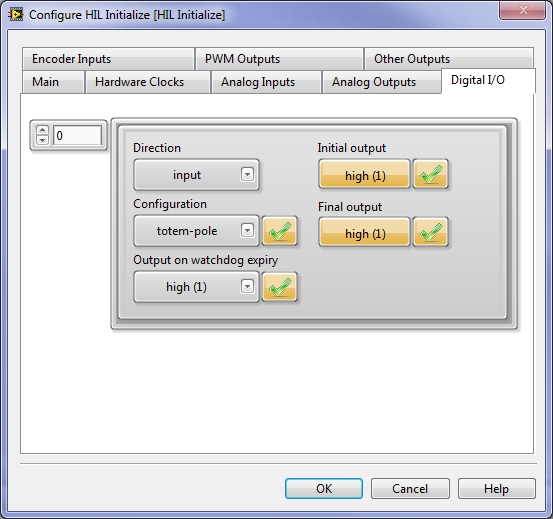
Direction
Select the direction of the digital I/O line. If this field is disabled then the specified channel does not support bidirectional digital I/O.
Configuration
Digital lines are typically open-collector outputs or totem-pole outputs. Some cards allow the configuration of digital outputs to be changed. The Configuration field allows the digital output configuration to be specified.
| If the button next to the Configuration field is checked, then the configuration of the digital output is programmed. If the button is not checked, but shows a red X, then the digital output configuration is not programmed but is left at its current value. |
Output on watchdog expiry
If a watchdog timer is used, then the value of the Output on watchdog expiry field is written to the specified digital output channel if the watchdog expires. This capability is extremely important for ensuring the safety of the control system. The digital line can be programmed to go low, high or tristate on watchdog expiry.
| If the button next to the Output on watchdog expiry field is checked, then the digital output channel is reset to the given value if the watchdog timer expires. If the button is not checked, but shows a red X, then the digital output channel is not programmed if the watchdog expires but is left at its current value. |
Initial output
The value of this field is written to the digital output channel when the HIL Initialize VI executes if the field is enabled.
| If the button next to the Initial output field is checked, then the value of the digital output is programmed when the HIL Initialize VI executes. If the button is not checked, but shows a red X, then the digital output channel is not programmed but is left at its current value. |
Final output
The value of this field is written to the digital output channel when the application stops if the field is enabled. The value is written whether the VI simply completes execution, or if it is aborted.
| If the button next to the Final output field is checked, then the value of the digital output is programmed when the application terminates. If the button is not checked, but shows a red X, then the digital output channel is not programmed but is left at its current value. |
Encoder Inputs
The Encoder Inputs tab is used to configure the encoder inputs of the card. The Encoder Inputs tab is depicted below:
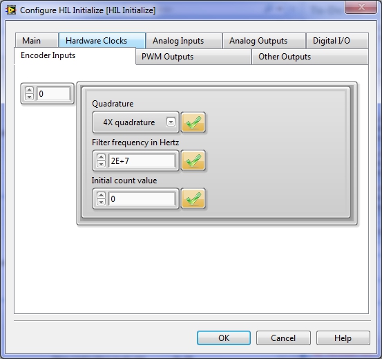
Quadrature
Use the HIL Initialize field to specify the type of quadrature used by the encoder input channel. In non-quadrature mode, the A and B signals of the encoder are treated as count and direction respectively. In 1X quadrature mode, the counter is incremented (or decremented) once for each full cycle of A (or B). In 2X quadrature mode, the counter is incremented (or decremented) twice for each full cycle of A (or B). In 4X quadrature mode, the counter is incremented (or decremented) four times for each full cycle of A (or B) because both the rising and falling edges of both A and B are used for counting. The normal quadrature mode for an encoder is 4X quadrature.
| If the button next to the Quadrature field is checked, then the encoder quadrature is programmed. If the button is not checked, but shows a red X, then the encoder quadrature is not programmed but is left at its current value. |
Filter frequency in Hertz
Some cards provide digital filtering of the encoder signals. This field allows the filter frequency to be set for those cards that support it.
| If the button next to the Filter frequency in Hertz field is checked, then the encoder filter frequency is programmed. If the button is not checked, but shows a red X, then the encoder filter frequency is not programmed but is left at its current value. |
Initial count value
Encoders are typically relative measurement devices. In general, the apparatus being controlled is placed in the home position and the block diagram run. This field allows the initial count value to be specified so that the encoder inputs are always relative to the home position.
| If the button next to the Initial count value field is checked, then the initial count value is programmed. If the button is not checked, but shows a red X, then the initial count value is not programmed but is left at its current value. This option is important when a calibration program is used to calibrate the encoders before the VI is run. |
PWM Outputs
The PWM Outputs tab is used to configure the PWM outputs of the card. The PWM Outputs tab is depicted below:
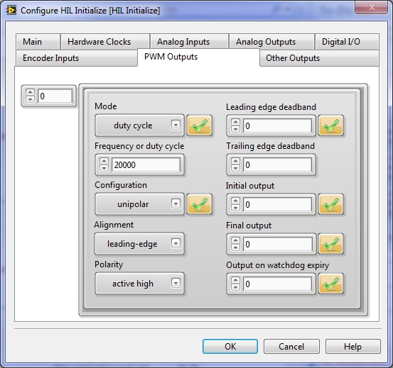
Mode
PWM outputs may operate in a variety of modes. Most cards only support the duty cycle mode, which is the typical mode for PWM outputs. However, some cards, like the Quanser QPID and QPIDe, support a wide variety of modes that are suitable for an assortment of applications. Valid modes are:
| Mode | Description |
|---|---|
| duty cycle | Writing to the PWM output varies the duty cycle of the PWM output. The PWM frequency is fixed at the value specified in the Frequency or duty cycle field. |
| frequency | Writing to the PWM output varies the frequency of the PWM output. The PWM duty cycle is fixed at the value specified in the Frequency or duty cycle field. |
| period | Writing to the PWM output varies the period of the PWM output. The PWM duty cycle is fixed at the value specified in the Frequency or duty cycle field. |
| one-shot | Writing to the PWM output varies the width of the PWM output. Only one single pulse is generated on the output for each write operation. |
| time | Writing to the PWM output varies the width of the PWM output pulse in seconds. The PWM frequency is fixed at the value specified in the Frequency or duty cycle field. |
| encoder | The PWM output emulates a full quadrature encoder when used with a complementary PWM output. Writing to the PWM output varies the emulated encoder velocity in counts per second. The duty cycle is fixed at the value specified in the Frequency or duty cycle field. |
| If the button next to the Mode field is checked, then the mode and frequency or duty cycle are programmed. If the button is not checked, but shows a red X, then they are not programmed but are left at their current values. |
Frequency or duty cycle
Determines the frequency or duty cycle of the PWM output. Whether it sets the frequency or duty cycle depends upon the PWM mode. This field sets the frequency of the PWM output for modes in which writing to the PWM output varies the duty cycle. It sets the duty cycle of the PWM output for modes in which writing to the PWM output varies the frequency.
Configuration
PWM outputs may also be configured in a variety of ways. The PWM output configuration determines how the channel interacts with other I/O on the card.
| Configuration | Description |
|---|---|
| unipolar | The PWM output is a unipolar signal appearing on a single output pin of the card. |
| bipolar | The PWM output modulates an analog output of the card so that the signal is bipolar. The amplitude of the signal is controlled by writing to the corresponding analog output. |
| paired | In the paired configuration, the PWM output is synchronized with another PWM output on the card, so that the "slave" output tracks the "master" output. In this configuration the deadband settings affect the behaviour of the slave channel relative to the master. |
| complementary | The complementary configuration is the same as the paired configuration except that the slave channel is inverted relative to the master. This configuration is useful for three-phase motor control and driving an H-bridge, particularly when the deadband settings are employed. |
| If the button next to the Configuration field is checked, then the configuration, alignment and polarity are programmed. If the button is not checked, but shows a red X, then they are not programmed but are left at their current values. |
Alignment
The alignment field determines how the PWM pulse is aligned within the PWM period. The alignments available are:
| Alignment | Description |
|---|---|
| leading-edge | The leading edge of the PWM pulse is aligned with the start of the PWM period. |
| trailing-edge | The trailing edge of the PWM pulse is aligned with the end of the PWM period. |
| centered | The PWM pulse is centered within the PWM period. |
Polarity
The polarity of the PWM output may be configured as active high or active low.
Leading edge deadband
The leading edge deadband is the time in seconds between the leading edge of the PWM pulse on the slave channel and the leading edge of the PWM pulse on the master channel, when the two channels are paired or complementary.
| If the button next to the Leading edge deadband field is checked, then the leading and trailing deadband are programmed. If the button is not checked, but shows a red X, then they are not programmed but are left at their current values. |
Trailing edge deadband
The trailing edge deadband is the time in seconds between the trailing edge of the PWM pulse on the slave channel and the trailing edge of the PWM pulse on the master channel, when the two channels are paired or complementary.
Initial output
The value of this field is written to the PWM output channel when the HIL Initialize VI executes if the field is enabled.
| If the button next to the Initial output field is checked, then the value of the PWM output is programmed when the HIL Initialize VI executes. If the button is not checked, but shows a red X, then the PWM output channel is not programmed but is left at its current value. |
Final output
The value of this field is written to the PWM output channel when the application stops if the field is enabled. The value is written whether the VI simply completes execution, or if it is aborted.
| If the button next to the Final output field is checked, then the value of the PWM output is programmed when the application terminates. If the button is not checked, but shows a red X, then the PWM output channel is not programmed but is left at its current value. |
Output on watchdog expiry
If a watchdog timer is used, then the value of the Output on watchdog expiry field is written to the specified PWM output channel if the watchdog expires. This capability is extremely important for ensuring the safety of the control system.
| If the button next to the Output on watchdog expiry field is checked, then the PWM output channel is reset to the given value if the watchdog timer expires. If the button is not checked, but shows a red X, then the PWM output channel is not programmed if the watchdog expires but is left at its current value. |
Other Outputs
The Other Outputs tab is used to configure other outputs of the card that do not fit within the standard categories. The Other Outputs tab is depicted below:
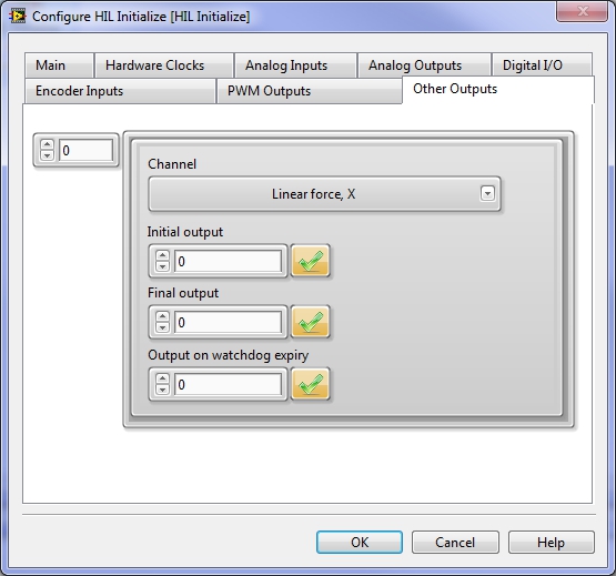
Channel
The Channel field cannot actually be modified. It shows the functionality of the channel currently selected by the array indexer.
Initial output
The value of this field is written to the other output channel when the HIL Initialize VI executes if the field is enabled.
| If the button next to the Initial output field is checked, then the value of the other output is programmed when the HIL Initialize VI executes. If the button is not checked, but shows a red X, then the other output channel is not programmed but is left at its current value. |
Final output
The value of this field is written to the other output channel when the application stops if the field is enabled. The value is written whether the VI simply completes execution, or if it is aborted.
| If the button next to the Final output field is checked, then the value of the other output is programmed when the application terminates. If the button is not checked, but shows a red X, then the other output channel is not programmed but is left at its current value. |
Output on watchdog expiry
If a watchdog timer is used, then the value of the Output on watchdog expiry field is written to the specified other output channel if the watchdog expires. This capability is extremely important for ensuring the safety of the control system.
| If the button next to the Output on watchdog expiry field is checked, then the other output channel is reset to the given value if the watchdog timer expires. If the button is not checked, but shows a red X, then the other output channel is not programmed if the watchdog expires but is left at its current value. |
Outputs

|
board out is a reference to a HIL Board instance that represents the open HIL board. This output is wired to the board in terminals of other HIL VIs. |
||||||

|
error out contains error information. If the error in cluster indicated an error, the error out cluster contains the same information. Otherwise, error out describes the error status of this VI.
|


Details
The HIL Initialize Express VI must be placed outside of a Control & Design Simulation Loop. The board out signal may then be wired to CL HIL VIs inside the Control & Design Simulation Loop.
Feedthrough Behaviour
This vi has no inputs to feedthrough.
Examples
| RCP HIL Analog Loopback Example | This example is a simple analog loopback test without CD&Sim, but it demonstrates a number of important features of RCP. | |
| RCP CL HIL Analog Loopback Example | This example is a simple analog loopback test, but it demonstrates a number of important features of RCP. | |
| RCP CL HIL Position Control Example | This example demonstrates how to use a PID controller to control Quanser's SRV02 experiment. |
Targets
|
Target |
Supported |
Comments |
|---|---|---|
|
Yes |
Fully supported. |
Copyright © Quanser Inc. This page was generated 2024-11-15. Submit feedback to Quanser about this page.
Link to this page.