
RCP CL HIL Watchdog Example
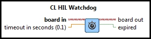
This example demonstrates how to use the HIL CL Watchdog VI as a safety feature when performing operations that may take too much time to compute and eventually freeze the system. It activates the watchdog timer of the HIL board. If the watchdog timer expires then the outputs of the HIL board will be reset to the values programmed in the HIL Initialize VI. For a detailed description of these VIs and how they operate, please refer to the RCP HIL Initialize, and CL HIL Watchdog help pages.
System Requirements
Please refer to the Rapid Control Prototyping (RCP) Toolkit System Requirements to run this example. This example requires data acquisition hardware with at least one set of Analog I/O channels and supported by the HIL Initialize VI, such as the Quanser Q2-USB hardware-in-the-loop card. Refer to the RCP Data Acquisition Card Support page for a full list of the RCP-supported HIL boards.
Configuring the Example
Open the RCP CL HIL Watchdog Example.vi under My Computer in the LabVIEW project.
To set up the example for a RCP-supported data acquisition card, select Show Block Diagram from the Window menu or press Ctrl+E
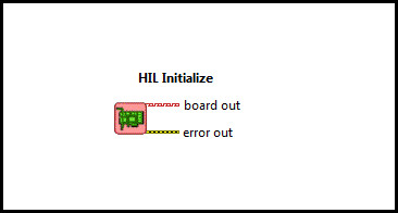
while the Front Panel is the active window. Double click the HIL Initialize VI and select the correct board type from the
Board type combo box. If you have more than one board of the same type in your computer, change the Board Identifier field to
the board you wish to use. Boards are numbered from 0 such that board 0 is the first board recognized by the HIL Initialize VI. Press
the to apply the changes and close the Configure HIL Initialize window.
Close the Block Diagram window after all changes to
the system have been made.
Connect an RCA cable from Analog Output #0 to Analog Input #0 on the terminal board.
Running the Example
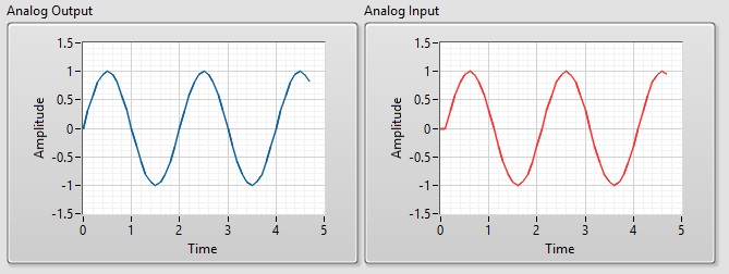
Click on the VI button or select from the menu to start the VI. A sine wave will
appear in the Analog Input and Analog Output graphs. The Analog Output graph displays the value
of the Analog Output Signal and the Analog Input displays the value measured from the Analog Input channel #0
from the PC data acquisition card.
The Analog Input graph should display the same signal as the
Analog Output graph because the input channel is connected to the output channel via the RCA cable.
Notice that the graph trace moving in real-time. In other words, the trace passes the 5-second mark after 5 seconds have passed.
If the Analog Input graph does not match with the Analog Output Signal and the Computation Load is set to LOW,
verify that the RCA cable from analog output #0 is properly connected to analog input #0 on the
corresponding RCA connectors and the HIL Initialize VI has the correct board type selected.
In this example, a subsystem is used to run intensive computations in order to create a load on the CPU. When the watchdog timer expires because timing constraints are not met, the board enters a "watchdog state" in which the outputs cannot be written. In this example, the timeout for the watchdog to expire is three times the step size in seconds.
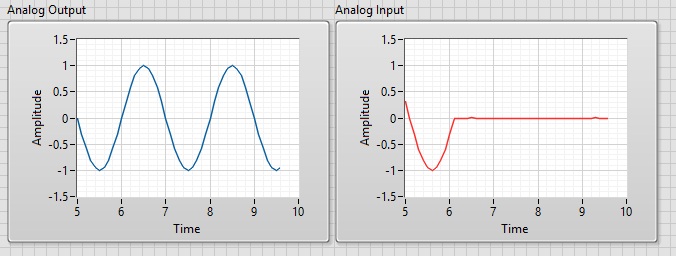
Setting the Computation Load to HIGH causes the board to enter the "watchdog state". This is when the Analog Input gets set to the value
programmed in HIL Initialize (default is 0). Set the Computation Load to HIGH by clicking on the Computation Load Toggle Switch on the Front Panel.
To allow outputs to be written to the board again, the watchdog state must be cleared. If the Watchdog is cleared when the computation load is set to HIGH,
the watchdog will expire right away. Set the Computation Load to LOW and Click on Clear Watchdog Output on the front panel of the VI.
![]()
Realize that the Analog Input and Output graphs are the same again. Click on the Front Panel button to stop the VI.
Copyright © Quanser Inc. This page was generated 2024-11-15. Submit feedback to Quanser about this page.
Link to this page.