
Optical Flow Sensor
Reads an optical flow sensor.
Library
QUARC Targets/Devices/Third-Party/Sensors MATLAB Command Line Click to copy the following command line to the clipboard. Then paste it in the MATLAB Command Window: qc_open_library('quarc_library/Devices/Third-Party/Sensors')
Description
The Optical Flow Sensor block reads the selected optical flow sensor and outputs the velocity detected in the X and Y directions.
For the PMW3901 sensor, a URI must be provided for an SPI communication channel connected to the sensor. However, only the SCLK, MOSI and MISO lines of the SPI port should be connected to the sensor. The slave select line, SS, or chip select, CS, should be wired to a digital output (GPIO) instead because of the non-standard timing of the PMW3901 sensor. Hence, the model must also contain a HIL Initialize block with the digital output configured on the Digital Outputs tab. The HIL board name associated with the HIL Initialize block and the digital output channel number must be set in the HIL board name and Digital output for CS parameters of the Optical Flow Sensor block respectively.
For example, to use a Bitcraze FlowDeck v2 PMW3901 sensor on the QDrone, choose a URI of spi://localhost:0?baud='2000000',polarity=on,phase=on,lsb=off,frame=0, a HIL board name of "HIL-1" and a Digital output for CS of "4" (CPU_GPIO_5). Place a HIL Initialize block in the model with the default name of "HIL-1" and on the Digital Outputs tab set the Digital output channels to "4" and the Initial digital outputs and Final digital outputs fields to "[1]".
Then connect the sensor as follows:
Wire GND to Ground (J7 pin 6)
Wire CS to CPU_GPIO_5 (J7 pin 5)
Wire VCC and VCOM to 3.3V (J5 pin 16 or J6 pin 2)
Wire MISO to SPI MISO (J5 pin 12)
Wire CLK to SPI SCLK (J5 pin 11)
Wire MOSI to SPI MOSI (J5 pin 9)
Leave MOTION and RESET unconnected
Input Ports
This block has no input ports.
Output Ports
vel
The velocity detected by the optical flow sensor as a double 2-vector containing the X and Y velocities. Integrating these velocities will provide the position relative to the location at model start, but the integrated velocities will be prone to drift. This output only appears when the Read image option is not checked.
img
The image frames detected by the optical flow sensor as a uint8 HxW matrix, where H is the height and W is the width. For example, for the PMW3901 sensor it is a 35x35 image. This output only appears when the Read image option is checked.
err
An int32 error code indicating any errors that have occurred. If there are no errors, then this output will be zero. See Error Codes for the different error codes and their values. Use the Compare to Error block rather than the error code itself to check for specific error codes.
Parameters and Dialog Box
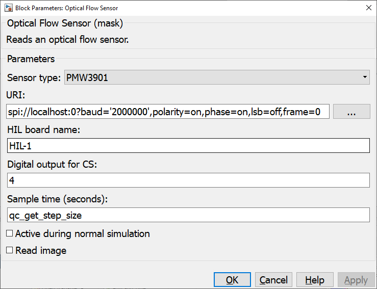
Sensor type
The type of optical flow sensor to which to interface.
URI
The URI of the communication channel connected to the optical flow sensor. For example, for a Bitcraze FlowDeck v2 the URI will reference an SPI communication channel, such as spi://localhost:0?baud='2000000',polarity=on,phase=on,lsb=off,frame=0
HIL board name
The name of the board whose digital output will be used as an SPI slave select signal. Boards are configured using the HIL Initialize block. Place an HIL Initialize block in your diagram and reference its board name in this parameter.
Digital output for CS (tunable offline)
The channel number of the digital output of the HIL board being used as the chip select for the sensor.
Sample time
The sample time of the block. A sample time of 0 indicates that the block will be treated as a continuous time block. A positive sample time indicates that the block is a discrete time block with the given sample time.
A sample time of -1 indicates that the block inherits its sample time. Since this is a source block, only inherent the sample time when it is placed in a conditionally executed subsystem, like a Triggered Subsystem, Enabled Subsystem, Function Call Subsystem or in a referenced model.
To use the fundamental sampling time of the model, set the sample time to qc_get_step_size, which is a QUARC function that returns the fundamental sampling time of the model.
The default sample time is set to qc_get_step_size.
Active during normal simulation (tunable offline)
Indicates whether this block should execute during normal simulation. If this option is not checked then the block will not listen for or accept connections during normal simulation. This parameter has no effect on generated code.
Read image
Whether to read motion data from the optical flow sensor or image data. Image data is often very slow (e.g. less than 1 Hz) to this option is typically only checked for debugging purposes to confirm what the sensor is seeing. Checking this option will change the output to an img output consisting of an HxW uint8 image.
Targets
|
Target Name |
Compatible* |
Model Referencing |
Comments |
|---|---|---|---|
|
Yes |
Yes |
||
|
Yes |
Yes |
||
|
Yes |
Yes |
||
|
Yes |
Yes |
||
|
Yes |
Yes |
||
|
Yes |
Yes |
||
|
Yes |
Yes |
||
|
Yes |
Yes |
||
|
Yes |
Yes |
||
|
Yes |
Yes |
||
|
Yes |
Yes |
||
|
Yes |
Yes |
||
|
Yes |
Yes |
||
|
Yes |
Yes |
Last fully supported in QUARC 2018. |
|
|
Rapid Simulation (RSIM) Target |
Yes |
Yes |
|
|
S-Function Target |
No |
N/A |
Old technology. Use model referencing instead. |
|
Normal simulation |
Yes |
Yes |
See Also
Copyright ©2026 Quanser Inc. This page was generated 2026-05-13. Submit feedback to Quanser about this page.
Link to this page.