
Quanser QDrone
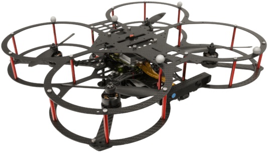
The Quanser QDrone is a drone built and sold by Quanser Inc. The QUARC Target associated with the QDrone is the QUARC Linux x64 Target. The QDrone driver provides access to the hardware I/O available on the QDrone platform. The QDrone includes an Intel Aero Compute board with an Intel Atom x7-Z8750 processor (2.56 GHz burst, quad core, 2M cache, 64 bit) and additional I/O supplied by Quanser. The additional I/O includes:
For more information, visit the Quanser website for the Quanser QDrone.
The QUARC driver name for this card is qdrone.
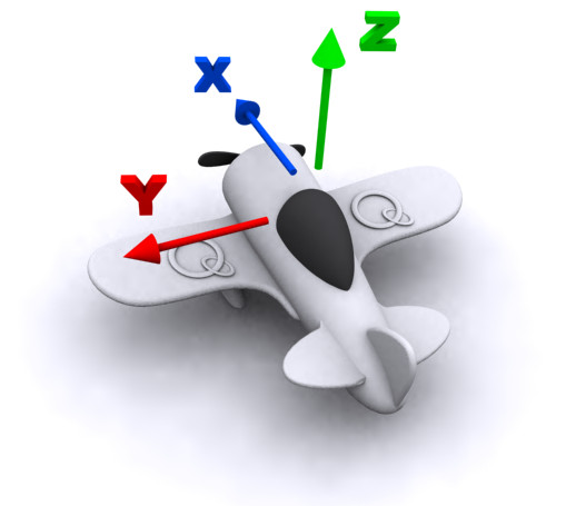
The QDrone uses the Quanser standard reference frame for UAVs, as shown below:
To select the QDrone board, select the QUARC qdrone board type from the drop-down list on the Main tab of the HIL Initialize block. Please note that only one QDrone card can be connected to a Quanser QDrone and is supported in the system. The QUARC controller runs on the Intel Aero Compute board and communicates with the QDrone hardware I/O via a 20 MHz SPI link.
| Note that the Linux x64 target must be selected to use the QDrone board, as it is connected to the Intel Aero Compute board. |
Cameras
The QDrone supports two onboard cameras. While these are accessed using the Video3D Capture and Video Capture blocks, they are listed here for convenience:
|
Camera |
Block |
Device Identifier |
Description |
|---|---|---|---|
|
RS200 |
Video3D Capture |
0 |
The RealSense R200 RGDB camera which faces toward the front of the QDrone. This camera supports four video streams: RGB, infrared left (0), infrared right (1) and depth. |
|
OV7251 |
Video Capture |
2 |
The OV7251 camera is a grayscale 640x480 camera with a global shutter. It faces down on the QDrone and is intended for visual odometry applications. |
The RealSense R200 colour (RGB) camera is a 2MP camera with up to 1920x1080 resolution. It has a 77° x 43° x 70° conical field of view. The frame rates achievable at each resolution are listed for convenience in the table below:
|
Resolution |
Maximum Frame Rate (FPS) |
|---|---|
|
1920x1080 |
30 |
|
1280x720 |
15 |
|
960x540 |
15 |
|
848x480 |
15 |
|
640x480 |
60 |
|
424x240 |
15 |
|
320x240 |
60 |
|
320x180 |
15 |
The RealSense R200 depth and infrared cameras have up to 640x480 resolution. They have a 70° x 46° x 59° conical field of view. The frame rates achievable at each resolution are listed for convenience in the table below:
|
Resolution |
Maximum Frame Rate (FPS) |
|---|---|
|
640x480 |
90 |
|
628x468 |
90 |
|
492x372 |
90 |
|
480x360 |
90 |
|
332x252 |
90 |
|
320x240 |
90 |
| Note that frame rates above 60 Hz may lose depth information due to the limited exposure time. To compensate for this, adjust the exposure manually. |
To increase the exposure time, use the Manal exposure option on the Camera Properties tab of the Video3D Capture block.
The OV7251 optical flow camera has up to 640x480 resolution. The frame rates achievable at each resolution are listed for convenience in the table below:
|
Resolution |
Maximum Frame Rate (FPS) |
|---|---|
|
640x480 |
30 |
Just about any smaller resolution larger than 32x32 is possible provided the width and height are even. The maximum frame rate is still 30 FPS.
Communications
The communications ports provided on the QDrone board can be utilized through the QUARC Communications blockset and the Quanser Stream API (see QUARC Communications Protocols).
For SPI communications, a sample URI for communications would be:
spi://localhost:0?baud='1000000',polarity='off',phase='off',lsb='off',frame='0'
where the frame option selects the SPI SS line to frame the SPI bus transaction (0, 1 or 2).
For I2C communications, a sample URI for communications would be:
i2c://localhost:0?baud='400000',address=0x69
where the address option specifies the I2C slave address.
For serial communications, a sample URI for communications would be:
serial://localhost:1?baud='115200',word='8',parity='none',stop='1'
where the port determines whether UART1 (port 1) or UART4 (port 4) is being used. UART1 is recommended for generic serial devices. It supports baud rates up to 4 MBaud. Use UART4 for devices which require polarity inversion of the TX and RX lines, such as S.BUS receivers, as UART4 supports a polarity option to invert its signal polarity. UART4 is more CPU intensive however, but does support baud rates up to 3.125 MBaud.
Clocks
There are currently no QDrone clocks.
Analog Inputs
The QDrone driver supports 5 analog inputs. Hence, analog input channel numbers range from 0 to 4. The analog input range is 0 to +3.3V and is not configurable. Exceeding this range may damage the board.
The battery level in Volts is reported at analog input channel 4. This signal should be monitored to ensure the battery does not degrade below safe levels, particularly for LiPo batteries. For instance, for a 3S battery, the voltage should not go below 10.5V.
Analog Outputs
The Quanser QDrone card does not support analog outputs.
Digital Inputs
The Quanser QDrone supports 5 bidirectional digital I/O lines. Hence digital input channel numbers range from 0 to 4. A digital I/O line cannot be used as an input and output at the same time.
Since the first 5 digital I/O lines may be individually programmed as inputs or
outputs on the Quanser QDrone, all of those 5 channels which will be used for digital inputs
should be configured on the HIL Initialize
block's Digital Inputs tab. Set the Digital input channels field to all
the digital I/O channels that will be used as digital inputs on the board for the current diagram. For example, enter
0:3 to designate channels 0 through 3 as digital inputs. Specify
[0, 4, 5] to indicate that channels 0, 4 and 5 are to be configured
as digital inputs.
Digital Outputs
The Quanser QDrone supports 5 bidirectional digital I/O lines and 19 LED lines. Hence digital output channel numbers range from 0 to 23. A digital I/O line cannot be used as an input and output at the same time.
Since the first 5 digital I/O lines may be individually programmed as inputs or outputs
on the Quanser QDrone, all the channels which will be used for digital outputs should be configured
on the HIL Initialize block's
Digital Outputs tab. Set the Digital output channels
field to all the bidirectional digital I/O channels that will
be used as digital outputs on the board for the current diagram. For example, enter
0:3 to designate channels 0 through 3 as digital outputs. Specify
[0, 4, 5] to indicate that channels 0, 4 and 5 are to be configured
as digital outputs.
To set the digital output values when the model is loaded or unloaded, set the Initial digital outputs and Final digital outputs to the desired values respectively. If the vectors specified in these fields are shorter than the channel vector, the value of the last element in the vector will be used for the rest of the channels. Hence, a scalar value will apply to all channels specified in the Digital output channels field.
The LED channels control the various LEDs on the board. The "Red LED", "Green LED", "Blue LED" and "Orange LED" are LEDs on the Intel Aero Compute board. The rest of the LEDS are on the top of the QDrone and are all RGB LEDs in which the individual red, green and blue components may be turned on or off.
Encoder Inputs
The Quanser QDrone supports three quadrature encoder inputs with 24-bit count values. Hence encoder channel numbers range from 0 to 2.
In order to set the encoder counters to a particular count or to change the default
quadrature when the model is loaded, the encoder inputs must
be configured on the HIL Initialize
block's Encoder Inputs tab. Set the Encoder input channels
field to all the encoder channels that will be
used on the board for the current diagram. For example, enter 0:2 to
indicate channels 0 through 2 are used as encoder inputs. Specify [0, 2]
to indicate that channels 0 and 2 are used as encoder inputs.
The Quanser QDrone supports non-quadrature (count and direction) and 4X quadrature. Since the Quanser QDrone has 24-bit counters, valid initial count values range from -8,388,608 to +8,388,607. If the vectors specified in these fields are shorter than the channel vector, the value of the last element in the vector will be used for the rest of the channels. Hence, a scalar value will apply to all channels specified in the Encoder input channels field.
The Quanser QDrone default sign convention in quadrature (4X) mode increments the encoder counter value when the B channel signal leads the A channel signal. Conversely, the encoder counter value is decreased when A leads B. This sign convention can be changed in the Board-Specific Options, with the enc0_dir option, for encoder channel 0, and with the enc1_dir and enc2_dir options for encoder channels 1 and 2, respectively. See the Board-Specific Options section below for more details.
PWM Outputs
The QDrone driver supports 8 PWM output channels. Hence, PWM output channels range from 0 to 7. Each PWM channel is completely independent and can have its own duty cycle and frequency.
| The first four channels (0-3) on the QDrone drive the four propellers and should be configured for OneShot125. The last four channels (4-7) are available to the user for whatever purpose is required. |
In order to configure the PWM mode or frequency, or to set the value of the PWM outputs when the model is loaded or unloaded, the PWM
outputs must be configured on the HIL Initialize block's
PWM Outputs tab. Set the PWM output channels field to all the PWM output channels that will be used on the
board for the current diagram. For example, enter 0:1 to indicate channels 0 and 1. Specify 1 to indicate channel 1 alone.
The PWM outputs are generic PWM outputs that are capable of producing the standard analog ESC protocols, namely standard PWM (1000us to 2000us), Oneshot125 (125us to 250us), Oneshot42 (42us to 84us) and Multishot (5us to 25us). The digital DSHOT protocol may also be used for any of the PWM outputs by setting the appropriate board-specific option. See the pwm0_dshot help for details. DShot150, DShot300, DShot600 and DShot1200 are all supported (and possibly faster).
The ESC Output block is recommended for constructing the input to the PWM output channel since it allows a 0% to 100% throttle value to be used, and it will output the appropriate pulse time (for PWM-based protocols) or raw value (in the case of DSHOT). Note that when using the ESC Output block, the PWM mode should be PWM_TIME_MODE (4) for PWM-based protocols and PWM_RAW_MODE (6) for DSHOT protocols.
The PWM parameters for each of these protocols are tabulated below:
|
Protocol |
PWM Frequency |
Pulse Time Range |
Duty Cycle Range |
|---|---|---|---|
|
Standard PWM |
50 Hz (20ms) |
0.001 to 0.002 seconds (1ms to 2ms) |
0.05 to 0.1 (5% to 10%) |
|
Oneshot125 |
2000 Hz (500us) |
125e-6 to 250e-6 seconds (125us to 250us) |
0.25 to 0.5 (25% to 50%) |
|
Oneshot42 |
5952 Hz (168us) |
42e-6 to 84e-6 seconds (42us to 84us) |
0.25 to 0.5 (25% to 50%) |
|
Multishot |
20000 Hz (50us) |
5e-6 to 25e-6 seconds (5us to 25us) |
0.1 to 0.5 (10% to 50%) |
|
DShot150 |
150000 Hz |
N/A |
N/A |
|
DShot300 |
300000 Hz |
N/A |
N/A |
|
DShot600 |
600000 Hz |
N/A |
N/A |
|
DShot1200 |
1200000 Hz |
N/A |
N/A |
|
DShot2400 |
2400000 Hz |
N/A |
N/A |
The PWM outputs are not restricted to these parameter values as they are generic PWM outputs. The maximum output frequency is 30 MHz. The number of bits of resolution decreases with increasing PWM output frequency.
Set the PWM output frequency (a.k.a., pulse rate) in the "Frequencies in Hz or duty cycle" field. The PWM output mode is typically set to duty cycle mode (0) or time mode (4) when driving ESCs or R/C servos. Set the Initial PWM outputs and Final PWM outputs fields to the desired initial and final output values respectively. The interpretation of these output values depends on the PWM mode selected. If the vectors specified in these fields are shorter than the channel vector, the value of the last element in the vector will be used for the rest of the channels. Hence, a scalar value will apply to all channels specified in the PWM output channels field.
Other Inputs
The specific Other Inputs channels of the QDrone board are described in the table below. SI units are used.
|
Other Input Channel |
Measurement Description |
Units |
|---|---|---|
|
3000, 3001, 3002 |
Angular velocity around the x-, y-, and z-axis, respectively (from gyroscope) |
(rad/s) |
|
4000, 4001, 4002 |
Linear acceleration along the x-, y-, and z-axis, respectively (from accelerometer) |
(m/s2) |
|
8000, 8001, 8002 |
Magnetic field along the x-, y-, and z-axis, respectively (from magnetometer) |
(T) |
|
9000 |
Pressure measurement from barometer. |
(Pa) |
|
10000 |
Temperature of barometer sensor. |
(C) |
Channel numbers for Other Input or Output channels use predefined ranges for each type of measurement to ensure consistency between data acquisition devices. Refer to QUARC Other Channels for a list of the Other Input or Output channel number ranges defined for any HIL Data Acquisition Card and their SI units.
Note that the barometer contains a 24-bit A/D and should be sampled at a slower rate than the other channels. The minimum sampling period for the barometer depends on the oversampling factor specified in the board-specific options. The following table shows the conversion times for the barometer for different oversampling ratios. The barometer should be sampled slower than these conversion times. Be aware that using smaller oversampling leads to a less accurate reading, so while it may be tempting to use the minimum oversampling to get the fastest response, the reading may be less useful. Both the pressure and temperature of the barometer are subject to these conversion times, but both values may be read in a single conversion time if they are being read by the same HIL Read or HIL Read Other block.
|
Oversampling Ratio |
A/D Conversion Times |
|---|---|
|
256 |
1.20 ms |
|
512 |
2.34 ms |
|
1024 |
4.56 ms |
|
2048 |
9.08 ms |
|
4096 |
18.08 ms |
Other Outputs
The Quanser QDrone card does not support other outputs.
Interrupts
The Quanser QDrone card, or its driver, does not support any interrupt sources.
Watchdog
The Quanser QDrone contains a programmable 16-bit watchdog timer. The timer may be programmed with any interval between 0.1 ms and 3.27675 seconds. The board will reset the PWM outputs to zero when the watchdog expires. The watchdog is also triggered when the ESC disable switch on top of the QDrone is set to disable the ESCs. Resetting of the outputs occurs without software intervention, and therefore may be used as a safety mechanism in the event of software failure. The PWM output values when the watchdog timer expires is not configurable.
There is also a second, non-programmable watchdog timer that expires after one second. This watchdog also resets the PWM outputs to zero. It is reset whenever hardware I/O is performed, other than bidirectional digital I/O.
Place a HIL Watchdog block in the diagram to program the 16-bit watchdog timer. This block also reloads the watchdog each time it is executed.
Once the watchdog has expired, further I/O is disabled until the watchdog state is cleared.
Hence, in Simulink models, the PWM outputs will remain zero after watchdog expiration even after the model is stopped, unless a HIL Watchdog Clear block is used to clear the watchdog state. Restarting the model also causes the watchdog state to be cleared, allowing the PWM outputs to be used once more. These semantics make the watchdog useful for ensuring product safety.
The switch on top of the QDrone also acts as a watchdog in the sense that if the switch is set to the "Disable ESCs" position then the PWM outputs are reset to 0V. When the switch is moved back to the enable ESC position the ESCs are only re-enabled once the watchdog state is cleared, as discussed above.
Board-Specific Options
The Quanser QDrone has a number of board-specific options to control specialized functionality of the QDrone. These options configure the IMU and set the encoder directions.
gyro_rate
This option sets the gyroscope sensor's sampling rate. Valid values range from 25 to 3200. The units are Hz.
gyro_os
This option determines the oversampling ratio used for the gyroscope's onboard filtering. Valid values are 1, 2 or 4.
gyro_fs
This option sets the full-scale range of the gyroscope sensor. Valid values range from 125 to 2000. The units are degrees per second.
accel_rate
This option sets the accelerometer's sampling rate. Valid values range from 12.5 to 1600. The units are Hz.
accel_os
This option sets the oversampling ratio used for the accelerometer's onboard filtering. Valid values are 1, 2 or 4.
accel_fs
This option configures the full-scale range of the accelerometer. Valid values are 2 to 16. The units are g's.
baro_os
This option sets the oversampling ratio of the barometer. Valid values range from 256 to 4096. While a lower oversampling ratio reduces the A/D conversion time and enables faster sampling of the barometer, it also reduces the accuracy. In general, use the highest oversampling ratio possible to ensure the best accuracy.
enc0_dir
Set this option to "yes", "y" or "1" to reverse the direction of encoder 0. This feature makes it easier to migrate to the Quanser QDrone hardware from another data acquisition card. It also allows models to be more portable to other cards.
Similar options exist for the other encoder channels i.e., enc1_dir and enc2_dir.
pwm0_dshot
Set this option to "yes", "y" or "1" to enable DSHOT on PWM output 0. When DSHOT is enabled, the only PWM mode supported is raw mode (6), and the input to the PWM output channel be a 16-bit value representing the bits of the DSHOT packet (where the most-significant bit is sent first).
This 16-bit value should be constructed using the ESC Output block with the DSHOT protocol selected. This block allows the throttle, telemetry request and command to be used to construct the 16-bit packet.
Similar options exist for the other PWM channels i.e., pwm1_dshot ... pwm7_dshot.
Properties
The Quanser QDrone card does not support any properties.
Connectors
The QDrone board has a number of connectors for expansion I/O. These connectors and their pinouts are listed below. Note that all pins are 3.3V and are not 5V tolerant unless marked otherwise. The analog inputs only support 0 to +3.3V. Exceeding these voltages may damage the board!
J4 Connector (ESCs)
Ground ― | 6 | 5 | → PWM0 |
NC ― | 4 | 3 | → PWM1 |
PWM3 ← | 2 | 1 | → PWM2 |
J5 Connector (SPI, I2C, UART1 and ADCs)
3.3V ― | 16 | 15 | ↔ I2C SCL |
Ground ― | 14 | 13 | ↔ I2C SDA |
SPI MISO → | 12 | 11 | → SPI SCLK |
SPI SS 0 ← | 10 | 9 | → SPI MOSI |
UART1 TX ← | 8 | 7 | ← UART1 RX |
ADC1 → | 6 | 5 | ← ADC0 |
ADC3 → | 4 | 3 | ← ADC2 |
SPI SS 1 ← | 2 | 1 | → SPI SS 2 |
J6 Connector (UART4, PWMs and ENCs)
5V ― | 16 | 15 | ← ENC1 B / DIR5 |
Reserved ― | 14 | 13 | ← ENC1 A / CNT5 |
ENC2 B / DIR5 → | 12 | 11 | ← ENC0 B / DIR5 |
ENC2 A / CNT5 → | 10 | 9 | ← ENC0 A / CNT5 |
UART4 TX ← | 8 | 7 | → PWM7 |
UART4 RX → | 6 | 5 | → PWM6 |
Ground ― | 4 | 3 | → PWM5 |
3.3V ― | 2 | 1 | → PWM4 |
5 5V tolerant input pins
J7 Connector (GPIO)
Ground ― | 6 |
CPU_GPIO_5 ↔ | 5 |
CPU_GPIO_4 ↔ | 4 |
CPU_GPIO_3 ↔ | 3 |
CPU_GPIO_2 ↔ | 2 |
CPU_GPIO_1 ↔ | 1 |
Legend
→▯← | = | input |
←▯→ | = | output |
↔▯↔ | = | bidirectional I/O |
= | 3.3V signal | |
= | power | |
= | ground | |
= | reserved |
Targets
|
Target |
Supported |
Comments |
|---|---|---|
|
No |
Not supported. |
|
|
No |
Not supported. |
|
|
No |
Not supported. |
|
|
No |
Not supported. |
|
|
No |
Not supported. |
|
|
No |
Not supported. |
|
|
No |
Not supported. |
|
|
No |
Not supported. |
|
|
No |
Not supported. |
|
|
No |
Not supported. |
|
|
No |
Not supported. |
|
|
No |
Not supported. |
|
|
No |
Not supported. |
|
|
No |
Not supported. |
|
|
No |
Not supported. |
|
|
Rapid Simulation (RSIM) Target |
Yes |
Supported with no communication to the hardware. |
|
Normal simulation |
Yes |
Supported with no communication to the hardware. |
Copyright ©2026 Quanser Inc. This page was generated 2026-05-13. Submit feedback to Quanser about this page.
Link to this page.
