
Quanser QBall 2
 This card is no longer available. For a newer card with much improved capabilities, visit the Quanser website
for the Quanser QDrone.
This card is no longer available. For a newer card with much improved capabilities, visit the Quanser website
for the Quanser QDrone.
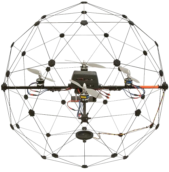
The Quanser QBall 2 is an Unmanned Aerial Vehicle (UAV) built and sold by Quanser Inc. The QBall2 is based around a dual-core 1 GHz ARM Cortex-A9 processor with 1 GB RAM running Yocto Linux. The QUARC Target associated with the QBall2 is the QUARC Linux DuoVero Target. The QBall2 HIL card may only be used with QUARC when this target is selected. The following characteristics are of particular interest when using the QBall2 with QUARC:
**The serial port is accessed through the Stream API blocks, see Serial protocol.
***The SPI port is accessed through the Stream API blocks, see SPI protocol.
****The I2C port is accessed through the Stream API blocks, see I2C protocol.
The QUARC driver name for this card is qball2.
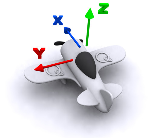
The Quanser QBall 2 uses the Quanser standard reference frame for UAVs, as shown below:
To select the Quanser QBall 2 HIL board, select the QUARC qball2 board type from the drop-down list on the Main tab of the HIL Initialize block.
| Note that the Linux DuoVero target must be selected to use the Quanser QBall 2 board. |
The Quanser QBall 2 I/O channels are described below.
Clocks
There are currently no configuration options for the Quanser QBall 2 clocks.
Analog Inputs
The Quanser QBall 2 supports 3 analog inputs. Hence, analog input channel numbers range from 0 to 2. The first two analog inputs have 0-5V range and 12-bit resolution. The last analog input channel is actually the battery voltage, which can be used to monitor when the battery voltage is getting low. The battery voltage range is 0-20V with 12-bit resolution.
Analog Outputs
The Quanser QBall 2 card does not support analog outputs.
Digital Inputs
The Quanser QBall 2 supports 8 reconfigurable digital I/O lines that may be used as digital inputs.
Digital Outputs
The Quanser QBall 2 supports 8 reconfigurable digital I/O lines that may be used as digital outputs.
It also supports two dedicated digital output lines. Digital channel 8 drives an onboard LED, and channel 9 is used to enable the quadrotor motors. An enable signal is provided so that the motors may be disabled without powering down the device, which is useful for motor calibration.
Encoder Inputs
The Quanser QBall 2 card does not support encoder inputs.
PWM Outputs
The Quanser QBall 2 driver supports two PWM output channels. Hence, PWM output channels range from 0 to 1.
In order to configure the PWM mode or frequency, or to set the value of the PWM outputs when the model is loaded or unloaded, the PWM
outputs must be configured on the HIL Initialize block's
PWM Outputs tab. Set the PWM output channels field to all the PWM output channels that will be used on the
board for the current diagram. For example, enter 0:1 to indicate channels 0 and 1. Specify 1 to indicate channel 1 alone.
The PWM output frequency (a.k.a., pulse rate) is suitable for a variety of applications, including driving additional R/C servos. To drive an R/C servo, set the PWM frequency to 50 Hz, which is equivalent to a PWM output period of 20 ms. Then drive a duty cycle between 0.05 and 0.10 to get a 1 ms to 2 ms pulse.
The initial and final PWM outputs may be set via the Initial PWM outputs and Final PWM outputs fields respectively.
For example, enter 0.075 to indicate a 7.5 % duty cycle. A 7.5% duty cycle (i.e., a 1.5-ms pulse width) typically corresponds to the neutral position for
R/C servos. If the vectors specified in these fields are shorter than the channel vector, the value of the last element in the vector will be used for the rest
of the channels. Hence, a scalar value will apply to all channels specified in the PWM output channels field.
Other Inputs
The Quanser QBall 2 supports eight other input channels. The other input channels are defined as follows:
|
Other Input Channel |
Description |
Units |
|---|---|---|
|
0 |
Sonar distance |
(m) |
|
3000 |
Gyroscope X-axis |
(rad/s) |
|
3001 |
Gyroscope Y-axis |
(rad/s) |
|
3002 |
Gyroscope Z-axis |
(rad/s) |
|
4000 |
Accelerometer X-axis |
(m/s2) |
|
4001 |
Accelerometer Y-axis |
(m/s2) |
|
4002 |
Accelerometer Z-axis |
(m/s2) |
|
10000 |
Temperature |
(°C) |
Channel numbers for Other Input or Output channels use predefined ranges for each type of measurement to ensure consistency between data acquisition devices. Refer to QUARC Other Channels for a list of the Other Input or Output channel number ranges defined for any HIL Data Acquisition Card and their SI units.
Other Outputs
The Quanser QBall 2 supports four other output channels, defined in the table below. The four channels drive the motors for the quadrator. Full throttle (100%) is represented by a real value of 1.0, while zero throttle (0%) is denoted by a value of 0.0. Quantities in between are used for intermediate throttle values.
|
Other Output Channel |
Description |
Units |
|---|---|---|
|
11000 |
Left motor throttle |
(%) |
|
11001 |
Right motor throttle |
(%) |
|
11002 |
Front motor throttle |
(%) |
|
11003 |
Back motor throttle |
(%) |
Channel numbers for Other Input or Output channels use predefined ranges for each type of measurement to ensure consistency between data acquisition devices. Refer to QUARC Other Channels for a list of the Other Input or Output channel number ranges defined for any HIL Data Acquisition Card and their SI units.
Interrupts
The Quanser QBall 2 card, or its driver, does not support any interrupt sources.
Watchdog
The Quanser QBall 2 supports a watchdog timer for resetting the outputs on watchdog expiry. Namely, the first nine digital output channels, the four other outputs (rotor motors) and the two PWM channels will be reset to zero on watchdog expiry. Resetting of the outputs occurs without software intervention, and therefore may be used as a safety mechanism in the event of software failure.
To enable the watchdog, place a HIL Watchdog block in the diagram.
Once the watchdog has expired, further I/O on the outputs is disabled until the watchdog state is cleared.
Use a HIL Watchdog Clear block to clear the watchdog state when the model is running. Restarting the model will also clear the watchdog state.
The watchdog timer may be programmed for any timeout period between 12.8 microseconds and 0.8389 seconds exclusive.
Board-Specific Options
gyro_bw
This option determines the low-pass filter cutoff frequency used by the gyroscope. The gyroscope uses a low-pass filter to reduce noise when it samples the sensors. Valid cutoff frequencies depend on the selected output data rate (see gyro_rate). Valid values range between 12.5 and 110 Hz. If a value is specified within this range then it chooses the closest bandwidth that is valid for the output data rate. The specific bandwidths available for each data rate are shown in the table below:
|
Output Data Rate (Hz) |
Valid Filter Bandwidths (Hz) |
|---|---|
|
100 |
12.5 or 25 |
|
200 |
12.5, 25, 60 or 70 |
|
400 |
20, 25, 50, or 110 |
|
800 |
30, 35, 50 or 110 |
gyro_fs
This option determines the full-scale range of the gyroscope. The gyroscope supports full-scale ranges of 250 deg/s, 500 deg/s or 2000 deg/s. The full-scale range should be specified in deg/s. If a value is chosen between 250 and 2000 deg/s that does not match a valid full-scale range then it chooses the closest range that encompasses the requested range.
| Note that the output of the other input channels for the gyroscope, however, will be in rad/s. |
gyro_rate
This option determines the output data rate (ODR) used by the gyroscope. The gyroscope has its own internal clock with which it samples the sensors. Valid rates are 100, 200, 400 or 800 Hz. If a value is chosen between 100-800 Hz that does not match a valid rate then it chooses the closest rate.
Properties
The Quanser QBall 2 card does not support any properties.
Targets
|
Target |
Supported |
Comments |
|---|---|---|
|
No |
Not supported. |
|
|
No |
Not supported. |
|
|
No |
Not supported. |
|
|
No |
Not supported. |
|
|
No |
Not supported. |
|
|
No |
Not supported. |
|
|
No |
Not supported. |
|
|
No |
Not supported. |
|
|
No |
Not supported. |
|
|
No |
Not supported. |
|
|
No |
Not supported. |
|
|
Yes |
Only supported with a QBall 2 device. |
|
|
No |
Not supported. |
|
|
No |
Not supported. |
|
|
No |
Not supported. |
|
|
Rapid Simulation (RSIM) Target |
Yes |
Supported with no communication to the hardware. |
|
Normal simulation |
Yes |
Supported with no communication to the hardware. |
See Also
Copyright ©2026 Quanser Inc. This page was generated 2026-05-13. Submit feedback to Quanser about this page.
Link to this page.
