
Creating Your First Visualization Part II - Animation and Hierarchies
This part of the visualization tutorial will build on Part I. If you would like to start from the results of Part I, you can open the model here MATLAB Command Line Click to copy the following command line to the clipboard. Then paste it in the MATLAB Command Window: qc_open_library('quarc_visualization_example_part_i_demo') . Now it is time to get something moving in the scene. If you would just like to see the end result of this section, you can open the completed model here MATLAB Command Line Click to copy the following command line to the clipboard. Then paste it in the MATLAB Command Window: qc_open_library('quarc_visualization_example_part_ii_demo') .
|
Note that Vista users will need to modify the default URI on the communications tab to |
Adding the Visualization Set Variables Block
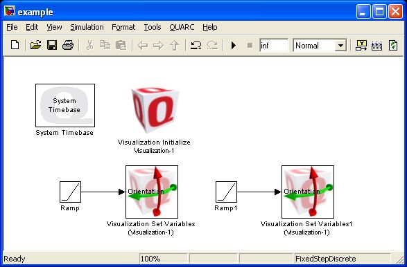
Begin by adding a Visualization Set Variables block from the QUARC Targets/User Interface/Visualization MATLAB Command Line Click to copy the following command line to the clipboard. Then paste it in the MATLAB Command Window: qc_open_library('quarc_library/User Interface/Visualization') library to your scene from Part I. Presently the block does not have any ports on it. Double-click on the block to open the Set Variables dialog.
You can see that the Visualization Set Variables block has already attached itself to Visualization 1. Visualization Set Variables blocks will always attach to the first Visualization Set Variables block in your scene. On the left side you can see our current actors: the camera, the light and the airplane. Double-click on the airplane to expand the tree view.
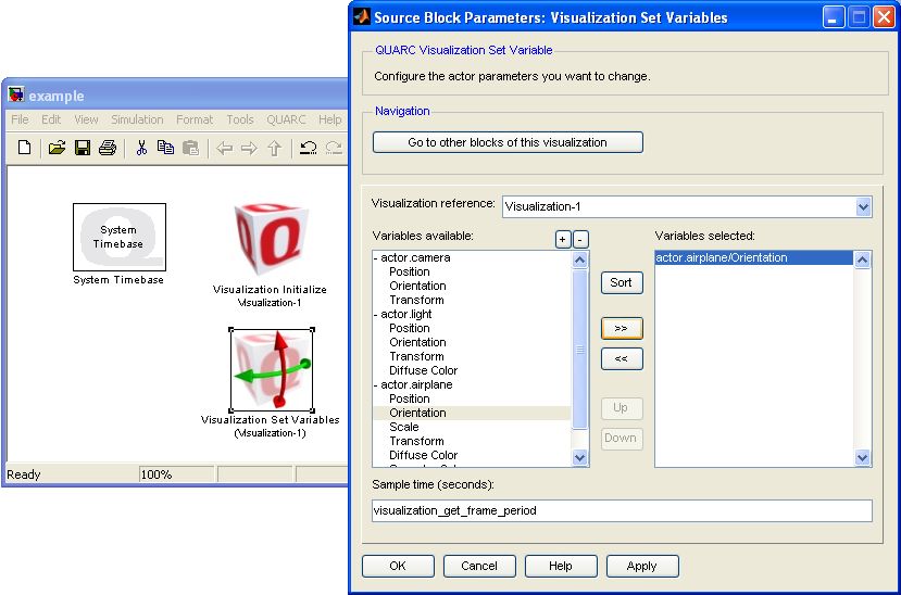
Our first animation example is going to rotate the airplane about the vertical axis, so select the Orientation property and then click the ">>" button. This will move the property over to the right-hand side. Click to close the dialog. You will now notice that there is a port on the Set Variables block.
Let's connect a Ramp source from the Simulink/Sources MATLAB Command Line Click to copy the following command line to the clipboard. Then paste it in the MATLAB Command Window: qc_open_library('simulink/Sources') library. Double click on the block and enter [0 0 1] for the Slope. This will rotate the airplane about the vertical (z) axis at the rate of 1 rad/s. (See the help page on the Quanser Standard Axes.)
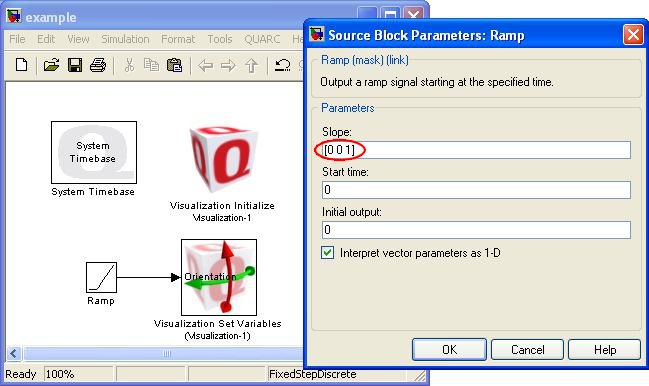
Run your model now and you should see your airplane rotating about the vertical axis. Congratulations, you have created your first animation!
| If your airplane viewer opened, but the airplane is not rotating, then the viewer has not been able to connect to the animation server in your diagram. If you are using Microsoft Vista as your operating system, then you may need to change the default URI. Open the Visualization Initialize block, and go to the Communications tab. If you are running in normal simulation, the URI should be shmem://%m:2?local='on'. If you are running in external mode, the URI should be shmem://%m:2?local='off' or shmem://%m:2. (Local is off by default.) |
Kinematic Relationships with Hierarchies
Visualizations are particularly useful for multibody systems. Interpreting graphs of position and velocity information while keeping track of the kinematic relationships can be daunting, but seeing what is happening as a collective system makes the relationships much clearer. You could create a multibody system by creating and controlling the position and orientation of every single actor in your scene, but this means that you would need at least 6 variables to drive the position and orientation, or potentially as many as 12 elements within a 4x4 matrix to drive the homogeneous transformation. Depending on the model of your system, it might be easier to link the actors kinematically and describe the motion of at least some of the actors relative to their parent's transformation.
To demonstrate this idea, open up the Visualization Initialize block and "Add
with actor" the airplane_propeller.x3d file from the
$(QUARC_DIR)/resources/meshes/mechanical/airplane
MATLAB Command Line
Click to copy the following command line to the clipboard. Then paste it in the MATLAB Command Window:
dos(sprintf('explorer.exe "%s" &', fullfile(qc_root, 'resources', 'meshes', 'mechanical', 'airplane')));
folder on the Mesh tab.
On the Object tab, edit object.airplane_propeller and change the Image resource to
point to image.airplane.
| On the Images tab, select image.airplane and click the button. You will notice on this texture map that it has various elements that you can see on the airplane including the Quanser logo, the engine, and the blue canopy. However, it also includes a texture for the propeller and the pilot. A single texture can be used by multiple meshes. In the case of the airplane, different meshes use different parts of the same texture map by selectively placing the texture coordinates in the CAD software used to create the meshes. Using a texture map this way is a convenient way to group your resources. |
If you run your model and navigate your view around to see the front of the plane, you will notice the propeller that we just added.
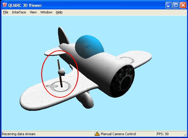
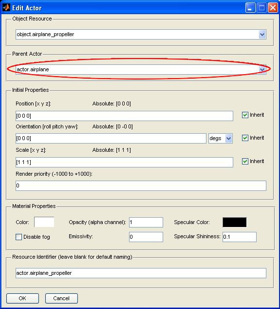
To attach the propeller to the body of the airplane, open the Visualization Initialize block and go to the Actors tab. Edit the actor.airplane_propeller and change the Parent Actor to be actor.airplane.
If you run your model now you will see that the propeller now moves with the airplane. Let's make one further addition to your model. Add another Set Variables block and add the actor.airplane_propeller/Orientation property. Connect another ramp source with a slope of [25 0 0] (rotation about the x-axis).
Run you model again and this time you should see the propeller spinning about the long axis of the airplane, but still moving with the airplane. We are driving the orientation of the propeller with respect to the orientation of its parent actor.
Advancing Further
This part of the tutorial has covered basic animation and one example of creating hierarchical relationships. However, this only covered a very simple example. Read on to PartIII to get a greater understanding of creating hierarchical relationships for more advanced kinematics.
Copyright ©2026 Quanser Inc. This page was generated 2026-05-13. Submit feedback to Quanser about this page.
Link to this page.

