
Creating Your First Visualization Part I - Loading Meshes and Textures
The QUARC Visualization blocks are made up of just two types of blocks (Visualization Initialize and Visualization Set Variables), but they give you immense power to provide full 3D visualizations of your simulations or real-time hardware. This page will cover the basics of how to setup your first visualization. If you would like to just see the end result of this section, you can open the completed model here MATLAB Command Line Click to copy the following command line to the clipboard. Then paste it in the MATLAB Command Window: qc_open_library('quarc_visualization_example_part_i_demo') .
|
Note that Vista users will need to modify the default URI on the communications tab to |
Creating a 3D visualization first requires 3D content. The content is a collection of meshes, which provide the geometry for an object in the scene, and textures, which are images that may be wrapped around a mesh. An object in the scene therefore consists of a mesh and an optional texture. These objects may be animated using actors. Actors consist of an object along with all the properties that allow that object to be integrated into the scene - position, orientation, material properties, etc.
Making your own meshes will be covered in the Content Creation, but for this example we will use content that is already included with QUARC from the Quanser/QUARC/resources folder.
Adding the Visualization Initialize Block
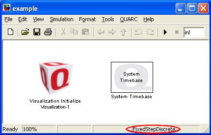
Let's begin by adding a Visualization Initialize block to your Simulink window from the QUARC Targets/User Interface/Visualization MATLAB Command Line Click to copy the following command line to the clipboard. Then paste it in the MATLAB Command Window: qc_open_library('quarc_library/User Interface/Visualization') library. In this introduction, we will only provide a brief overview of the features of this block. For full details, refer to the Visualization Initialize block reference page. Let's also add a System Timebase block from the QUARC Targets/Advanced/Timing MATLAB Command Line Click to copy the following command line to the clipboard. Then paste it in the MATLAB Command Window: qc_open_library('quarc_library/Advanced/Timing') library. For the purposes of this introduction, normal simulation will make it easier to quickly test changes without rebuilding. Instead of the simulation running as fast as it can, the System Timebase block will make the simulation progress in real-time so our animations will progress at the expected speed. Finally, from the menu, select and set the Solver type to "Discrete (no continuous states)" to eliminate the typical warning in the main Matlab window.
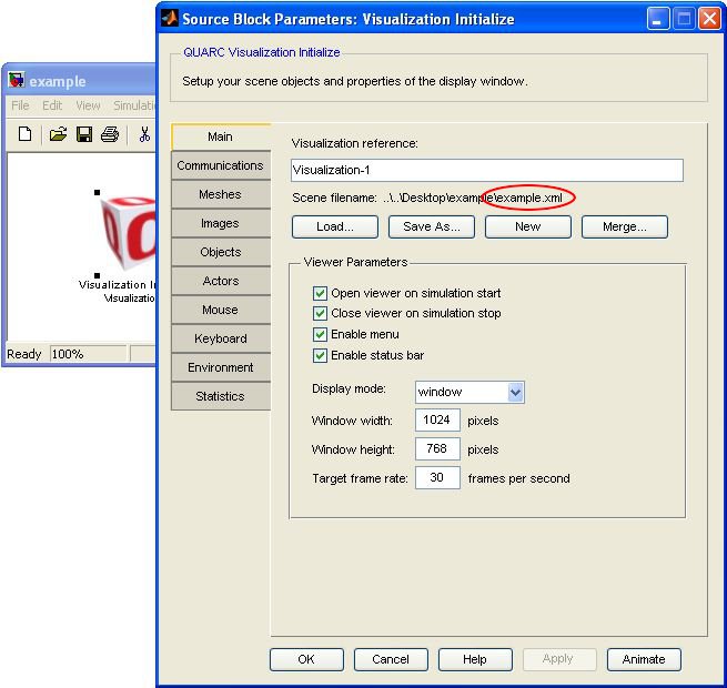
The main purpose of the Visualization Initialize block interface is to create a scene file for you and handle subsequent communications between your real-time or simulated model and the visualization interface. After adding the block to your diagram, double click on it to bring up the interface. The first tab you are presented with lets you set the name of the interface which will be referred to by all the Set Variables blocks and to select the name of the xml scene file. Let's begin by clicking on the button and save the filename as example.xml.
| If you are using Microsoft Vista as your operating system, you will need to make one additional change. On the Communications tab, change the default URI to shmem://%m:2?local='on'. See the Visualization Initialize block reference for more information on the communications options and considerations. |
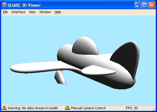
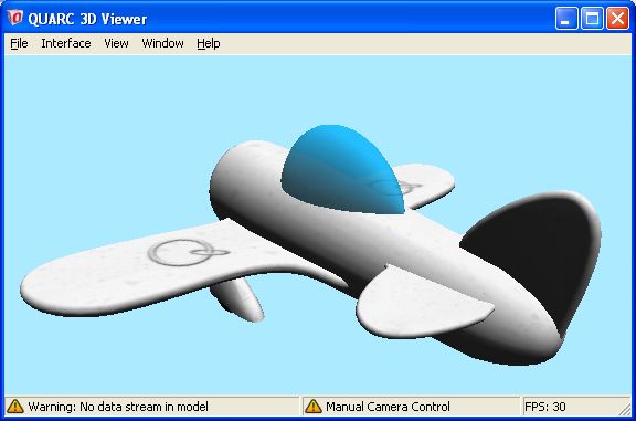
Finally, click to close the Visualization Initialize dialog. If you now run your model by going to the menu and selecting , you should see a window as shown below.
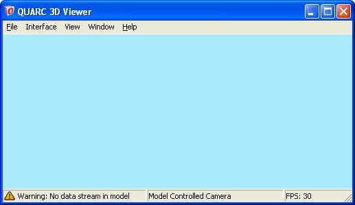
The window has the default color from the Environment tab, it is running at 30 frames per second (fps) which was specified on the Main tab, and the warning in the lower left tells us that although it has successfully connected to the visualization server, there is no data to transmit to the viewer. This means that there are no Set Variables blocks in our scene yet. If the lower left status says "Connecting..." then a connection has not yet been established to the server. If you are running Microsoft Vista for your operating system, then the shared memory option is not yet configured properly (see note above).
Other than this very nice blue environment, there is not much to see. Let's start adding content to the environment next.
Adding a Mesh
To start, we will add a single actor to our scene. If you haven't already, stop your model (by default, this will automatically close the viewer). Now open the Visualization Initialize dialog again and navigate to the Meshes tab. Clicking the add mesh button will bring up another dialog where you can either enter the path to the model manually or use the "..." button to the right of the text entry field. Clicking on this button will bring up an open file dialog box where you can navigate to the desired model. In this case, add airplane.x3d from the resources folder of the install location of QUARC (e.g. $(QUARC_DIR)/resources/meshes/mechanical/airplane MATLAB Command Line Click to copy the following command line to the clipboard. Then paste it in the MATLAB Command Window: dos(sprintf('explorer.exe "%s" &', fullfile(qc_root, 'resources', 'meshes', 'mechanical', 'airplane')));).
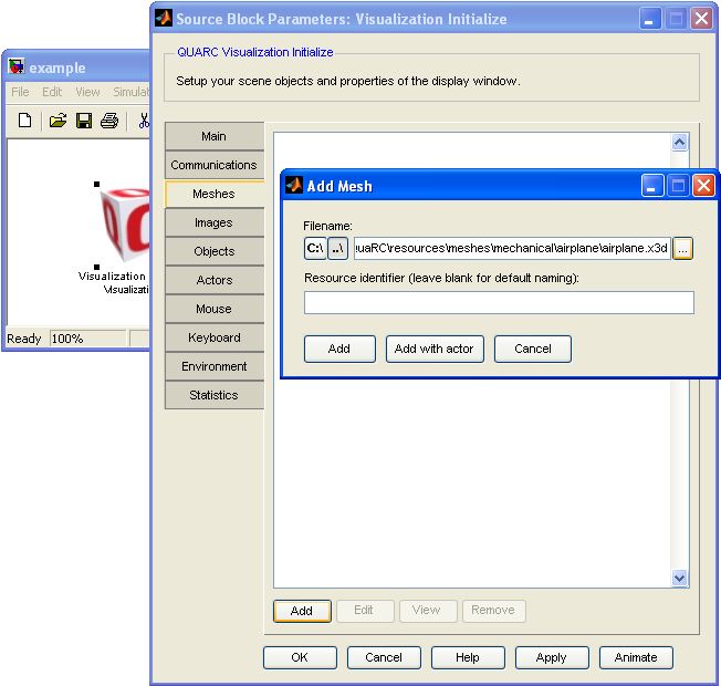
The "C:\" and "..\" buttons on the left allow you to switch between the absolute path and the relative path respectively. If a path relative to your scene file cannot be determined, then an absolute path will be used.
| Relative paths are particularly useful if you store all your models and textures in sub folders relative to your scene file. This makes it easier to send a model to someone else. |
To make efficient use of memory, the visualization block loads resources into a common pool. You can then connect textures to meshes using objects, and finally you can create multiple actors from a single object. Although you can manually create each level of this hierarchy, we can let the block do most of the work for us by clicking the button. Click the button now. This option automatically creates an object and actor from the mesh. Click the button to close the Visualization Initialize dialog and save the changes.
You can try the simulation now by clicking from the menu. Your initial view of the plane should be from behind looking at the tail. By using the A, S, W, and D keys to translate the camera, and clicking and dragging the mouse to rotate the camera view, you can manually move the camera around the environment for a better view as shown below.
If you look at the middle pane of the status bar, you will notice that the text has changed from "Model
Controlled Camera" to a warning icon with the text "Manual Camera Control". This means you are moving
freely from the camera actor and therefore independent of any camera motions created in Simulink. Hitting
Esc on your keyboard will return to the model-controlled camera.
At the moment, the airplane just has a base white color and is shaded based on the single light in the scene. Let's improve on this by adding a texture map.
Adding a Texture
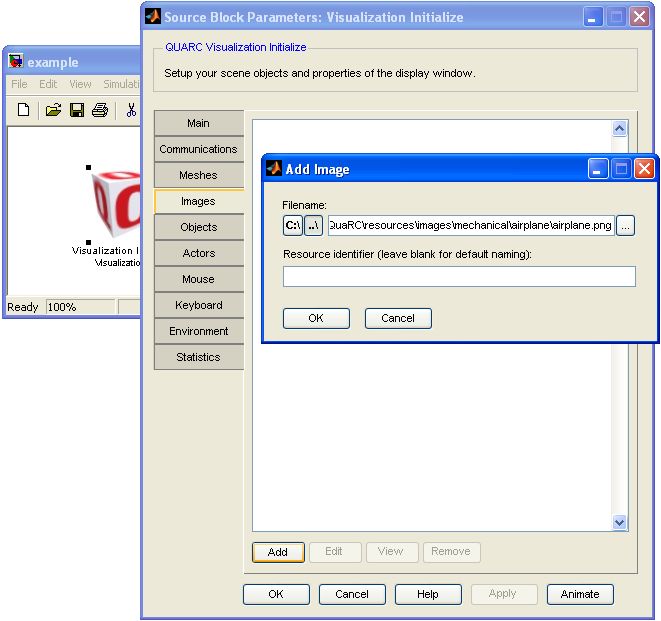
Adding a texture works in a similar manner to adding meshes. Again, stop your model, then open the Visualization Initialize block and navigate to the Images tab and click on the add texture button.
Again, this will bring up another dialog where you can enter the path to the texture resource. Click on the button to the right of the text entry and navigate to the image resources folder (e.g. $(QUARC_DIR)/resources/images/mechanical/airplane MATLAB Command Line Click to copy the following command line to the clipboard. Then paste it in the MATLAB Command Window: dos(sprintf('explorer.exe "%s" &', fullfile(qc_root, 'resources', 'images', 'mechanical', 'airplane')));) to find airplane.png. You can either manually give this texture a name, or leave it blank and a name will automatically be assigned based on the filename. Leave the name blank and click .
You will notice that a new image has been added to the resource pool with the ID "image.airplane". Selecting the image and clicking the button will give you a preview of the image. Opening the image in an image editing program such as the open-source GIMP (www.gimp.org) will reveal a bit more information as shown below.
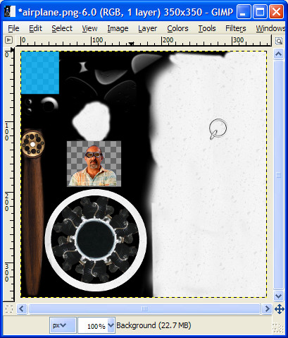
The checker pattern in GIMP indicates that there are some areas of this texture map that are partially or wholly transparent. The details of how the bitmap is actually mapped onto a mesh are controlled by the "texture coordinates" element in the x3d mesh file. The creation of these coordinates is handled by the software used to create the mesh in the first place, such as Autodesk's 3ds Max (www.autodesk.com) or the open-source Blender (www.blender.org). For more details see the help page on Content Creation.
Editing the Object
Switching to the Objects tab, you will see that we already have an object there called "object.airplane" that was created when we clicked back on the Mesh tab. Double-clicking on the airplane object (or selecting and clicking the button) will bring up another dialog where you can see that the airplane mesh is currently selected, but no texture is selected. From the texture drop-down box, select "image.airplane" and click .
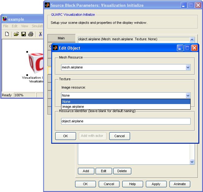
Click on the Visualization Initialize dialog and run the model again. Navigating around the scene you can now see that the airplane has some subtle texturing applied to the body, the Quanser logo is on the wings, and the canopy has become blue and semitransparent.
Editing an Actor
Every time that we have started the model, the visualization always starts with the same default positions. Let's say that we want to place the camera a bit closer and above, looking down on the airplane. Changing to the Actors tab, click on the "actor.camera" and then click on the button to bring up the Edit Actor dialog.
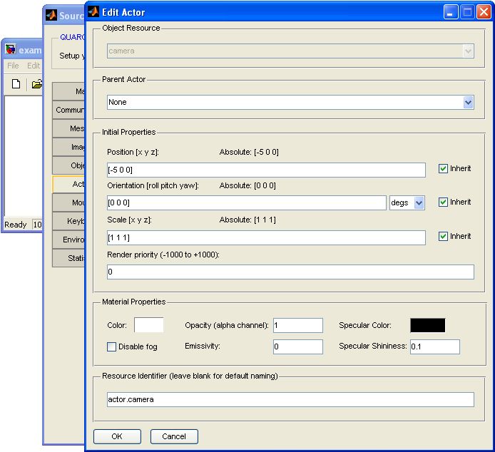
We could manually enter values for the initial position and orientation but without a clear understanding of the relationship between the camera and the airplane this would be rather difficult (this is useful when you know the precise distance that you want between objects). Instead, close the Edit Actor dialog and click the button at the bottom of the Visualization Initialize dialog.
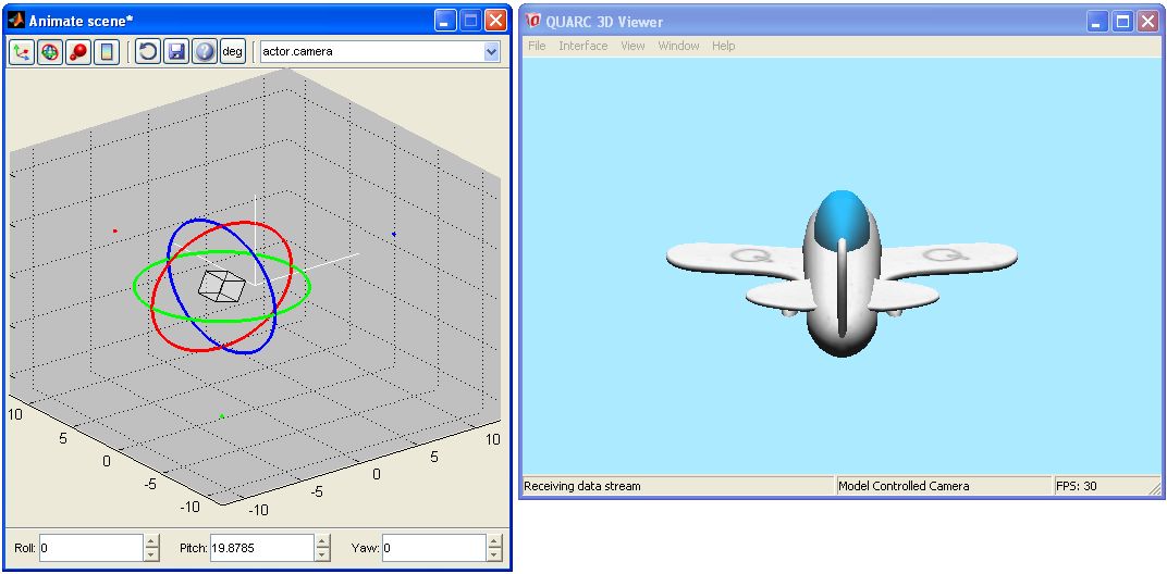
This will again bring up your visualization window, but this time it will be accompanied by an additional control window. Selecting the first control on the toolbar (selected by default when the control window is opened) will give you three axes and two planes on which you can drag the object around. Hover over the blue axis until it turns white, then drag it to the right and you will see your view update in real-time as the camera position is changed. Next grab the green axis to move the camera up. (Alternatively, you could have grabbed the yellow plane between the blue and green axes to move the camera in both directions simultaneously).
Next, select the second icon from the toolbar. This is the rotation control. Grab the red ring to rotate the camera downward slightly until you achieve a satisfying camera position. Finally, click the save disk icon and close the Animate Scene window. (For more details of the features available from this dialog, see the Animate Scene help page.) If you do not click the save icon, then it will ask whether you wish to save the changes to the scene. Once back at the Visualization Initialize dialog, click the button to save the changes to the scene file. If you run your model again, you will see that the initial position of the camera is now set to the new view.
Advancing Further
We have now covered the basics of loading meshes and textures to create objects and actors. Next we will look at animation in PartII.
Copyright ©2026 Quanser Inc. This page was generated 2026-05-13. Submit feedback to Quanser about this page.
Link to this page.

