
Creating Your First Visualization Part III - Dummy Actors
This part of the visualization tutorial examines hierarchies in greater depth to build on the theory we started in Part II. Setting the origins of your meshes is important to make sure that your kinematic relationships work as intended. If that is not possible, then we can add dummy actors to shift the apparent origin of our actors and create intermediate reference frames. If you would like to just see the end result of this section, you can open the model here MATLAB Command Line Click to copy the following command line to the clipboard. Then paste it in the MATLAB Command Window: qc_open_library('quarc_visualization_example_part_iii_demo') .
|
Note that Vista users will need to modify the default URI on the communications tab to |
Understanding Hierarchies in Greater Depth
Although the kinematic relationship in part II was perfectly valid, some of the intricacies were glossed over. The only property we changed of the propeller was the parent relationship, but how did the propeller know where to attach onto the plane? In the picture below, a mesh called "arrows.x3d" was also added to the scene at the origin.
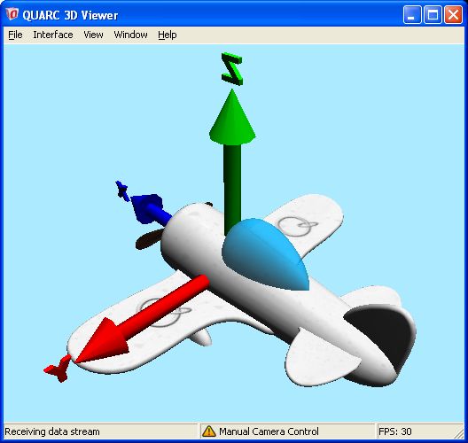
The arrows show the origin of both the plane and the propeller. The center of the propeller was aligned with the x-axis. Therefore, when we rotated the propeller about the x-axis, we were also rotating about the airplane body's x-axis. The offset along the x-axis was done during the creation of the object to simplify the assembly for the visualization. As a general rule though, place the origin of your meshes at the joint closest to the base joint.
| The arrows.x3d mesh (attached to the palette.png image) is a useful tool to figure out your frames. If you have many frames in your system, attach an arrows actor to each frame as a child object so you can get a better understanding of the orientations and origins in your system. |
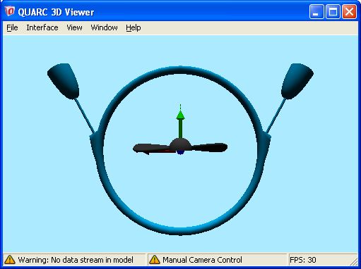
Let's examine a more realistic example of creating hierarchies. Create a new model and add a Visualization Initialize block and system timebase block. Open the Visualization Initialize dialog, navigate to the Meshes tab and "Add with actor" aerial_ring_ring.x3d, aerial_ring_propeller.x3d from the $(QUARC_DIR)/resources/meshes/mechanical/aerial_ring MATLAB Command Line Click to copy the following command line to the clipboard. Then paste it in the MATLAB Command Window: dos(sprintf('explorer.exe "%s" &', fullfile(qc_root, 'resources', 'meshes', 'mechanical', 'aerial_ring'))); folder, and arrows.x3d from the $(QUARC_DIR)/resources/meshes/user_interface/arrows MATLAB Command Line Click to copy the following command line to the clipboard. Then paste it in the MATLAB Command Window: dos(sprintf('explorer.exe "%s" &', fullfile(qc_root, 'resources', 'meshes', 'user_interface', 'arrows'))); folder (refer to Part I if you need a refresher on how to do this). On the Images tab, add palette.png from the $(QUARC_DIR)/resources/images/palettes MATLAB Command Line Click to copy the following command line to the clipboard. Then paste it in the MATLAB Command Window: dos(sprintf('explorer.exe "%s" &', fullfile(qc_root, 'resources', 'images', 'palettes'))); folder. Edit each of the three objects and attach image.palette to each of them. (For Vista users, don't forget to modify your URI as well.) Now run your model and you should see something like the following picture:
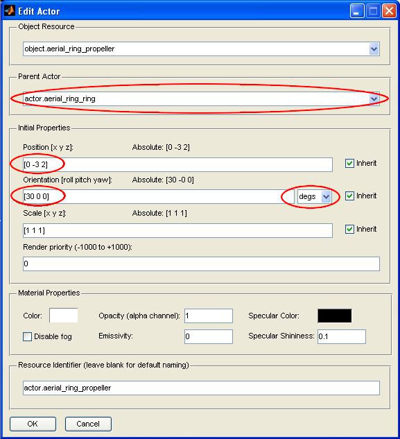
Unlike our example from Part II where everything was nicely aligned for us already, these kinematics are going to take a bit more work, but for good reason. In this case, we want to use the same propeller in two locations and at two different angles. More precisely, for the first propeller, we want it 2 units up (z), and 3 units right (-y) at an angle of 30 degrees about the x axis. So let's try this. Edit the actor properties of the actor.propeller. Set the parent to actor.aerial_ring_ring, set the position to [0 -3 2], and set the orientation to [30 0 0] while checking that the units are in degrees.
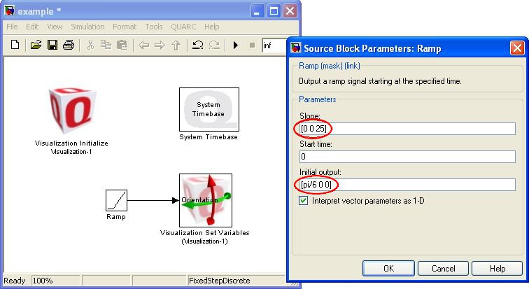
If you run that model, then the propeller will appear in the correct position. Let's add a Set Variables and Ramp block to drive the orientation of the propeller. Set the slope to [0 0 25] and the initial output to [pi/6 0 0] (to maintain the initial orientation we set in the actor properties).
Running your model now will result in the propeller wobbling about the axis instead of just turning about the intended axis, but at least it is wobbling about the right location. The transformation operations when specified individually occur in the order of translation, scale, roll (x), pitch (y), and finally yaw (z). The intention had been to rotate the propeller about its local axis, not the global axis, but since the roll operation occured first, this was not the case. There are a few options now. We could either specify all the orientations taking into account the order of operations, but that can be quite difficult. Alternatively, we could feed a transformation matrix in that is formed in such a way that the rotation occurs about the intended axis (see Composing your own transformation matrix for some helper blocks that make this process easier). The last option which we will explore here is the use of dummy actors.
Dummy Actors, The Smart Thing To Do
Dummy actors are one of the four catagories of actors. They are not associated with any mesh, but they can be shown by turning them on from the menu on the 3D viewer (they will appear as an outlined unit box, but scaled based on the current scale factor of the actor). Their main purpose is to create additional frames to simplify the transformations made to child actors. Depending on your target, dummy actors can actually reduce the computational load on your target by moving some of the matrix formation from the controller to the viewer instead.
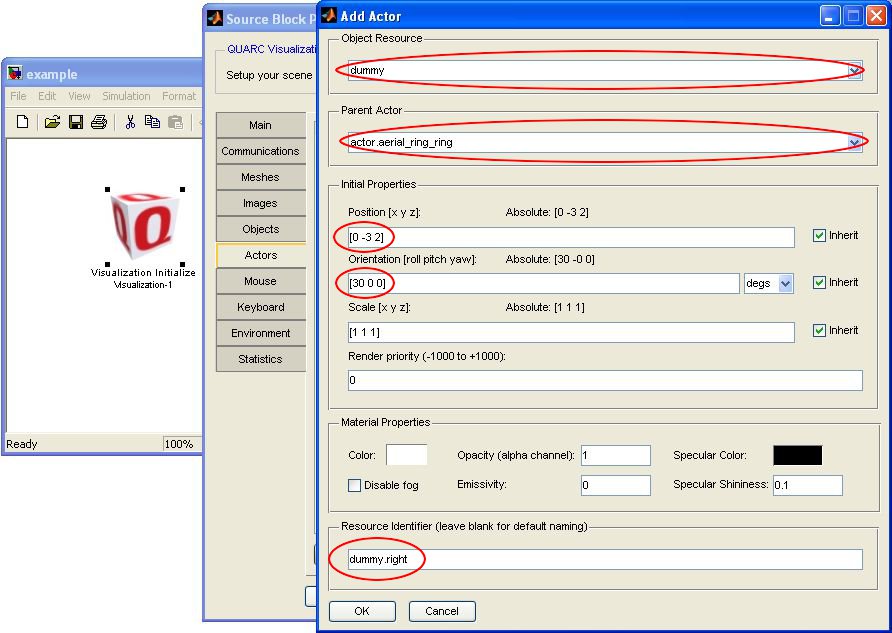
On the Actors tab, add a new actor of Object Resource type "dummy", set the Parent Actor to actor.aerial_ring_ring, Position to [0 -3 2], and Orientation to [30 0 0] in degrees. Rather than letting the name be auto-generated, enter the name "dummy.right" for the Resource Identifier.
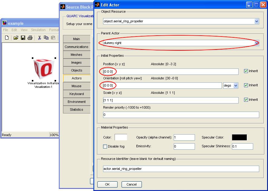
Now, edit the propeller actor. Set the Parent Actor to dummy.right, and the Position and Orientation to [0 0 0] since this transformation is now taken care of by the dummy actor.
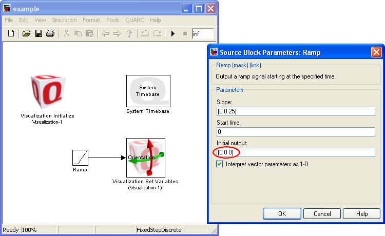
Finally modify the Ramp block to remove the initial condition.
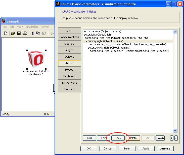
If you run your model again, you should now see the propeller spinning about the intended axis. Just to finish off this model, we're going to add another dummy actor and propeller, but since we have already set up the hierarchy for one propeller and dummy actor, we can just duplicate it without re-entering all the information. On the Actors tab of the Visualization Initialize block, select dummy.right and click the button. This will duplicate the actor and all of its children.
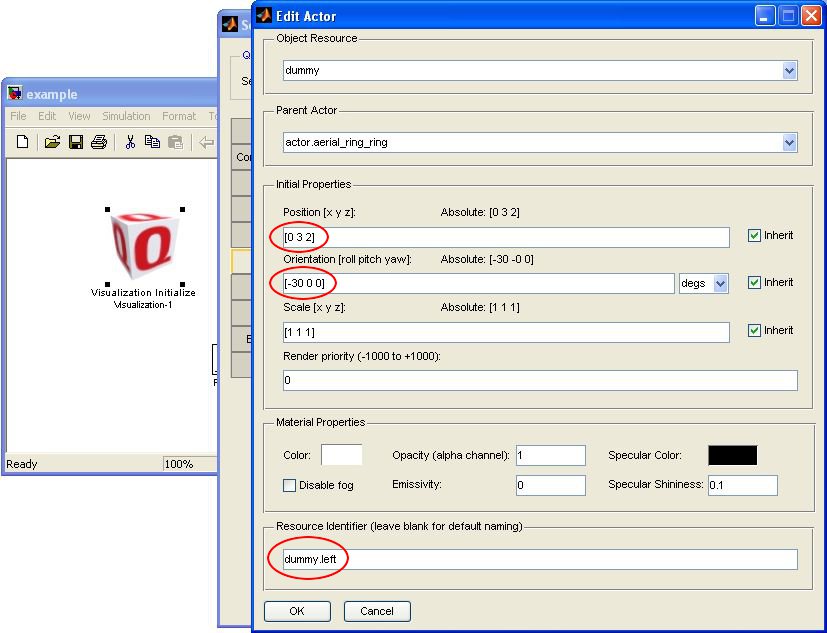
Edit the new dummy and change the Position to [0 3 2] (positive y), the Orientation to [-30 0 0], and the Resource Identifier to dummy.left.
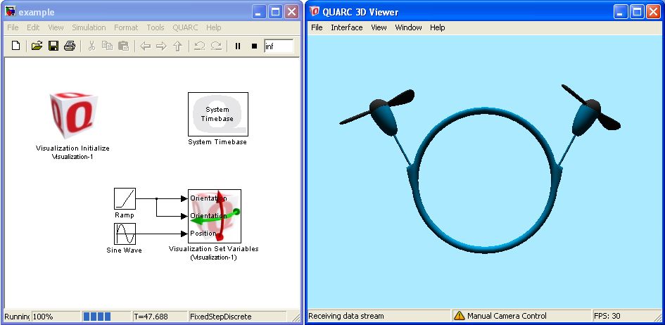
On the Set Variables block, add the orientation for the new propeller followed by the position of actor.aerial_ring_ring. Click to close the dialog and you will now have 3 ports on the Set Variables block. (The ports are in the same order as the Variables Selected list). Connect the ramp signal to the other propeller and a Sine Wave block with an amplitude of [0 0 0.1] to the actor.aerial_ring_ring/Position. Run you model again and you should see both propellers spinning and the ring bobbing up and down slightly.
Advancing Further
This example is a fairly realistic example of the use of hierarchies. If you can't pre-align components in your modelling software, then you must connect them together in the Visualization Initialize. Sometimes things can be simplified though through the use of dummy actors to create intermediate frames. The same process can be used create an entire robot arm with joint level control. However, what if you want to set the angle of a robot's arm with respect to a world frame instead of relative to the reference frame of the parent? This is what we will use selective inheritance for in PartIV.
Copyright ©2026 Quanser Inc. This page was generated 2026-05-13. Submit feedback to Quanser about this page.
Link to this page.

