
RCP CL HIL Position Control Example
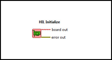
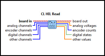
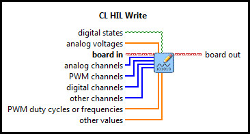
This example demonstrates how use a PID controller to control Quanser's SRV02 experiment. This experiment demonstrates a number of important features of RCP, such as the ability to access and quickly change hardware, online parameter tuning, data streaming, and potentially more. For a detailed description of these VIs and how they operate, please refer to the RCP HIL Initialize, CL HIL Read and CL HIL Write help pages.
System Requirements
Please refer to the Rapid Control Prototyping (RCP) Toolkit System Requirements to run this example. This example requires data acquisition hardware supported by the HIL Initialize VI, such as the Quanser Q2-USB hardware-in-the-loop card. Refer to the RCP Data Acquisition Card Support page for a full list of the RCP-supported HIL boards.
This example also requires, for example, Quanser's SRV02 rotary servo experiment with a Quanser VoltPAQ and corresponding connection cables.
The position of the motor is read from encoder channel 0 (i.e., EI #0).
Analog output channel 0 (i.e., AO #0) is used to drive the motor.
Therefore, the analog output channel #0 should be wired to the Quanser VoltPAQ (or UPM) power amplifier driving the SRV02 servo plant
and the SRV02 encoder should be wired to encoder input channel 0.
Configuring the Example
Open the RCP CL HIL Position Control Example VI under My Computer in the LabVIEW project.
To set up the example for a Quanser data acquisition card, select Show Block Diagram from the Window menu or press Ctrl+E
while the Front Panel is the active window. Double click the HIL Initialize VI and select the correct Board type from the
Board type combo box. If you have more than one board of the same type in your computer, change the Board identifier field to
the board you wish to use. Boards are numbered from 0 such that board 0 is the first board recognized by the HIL Initialize VI. Press
the to apply the changes and close the Configuring HIL Initialize dialog window. Close the Block Diagram window after all changes to
the system have been made.
Running the Example
Click on the button or select from the menu to start the VI.
The SRV02 position is driven by a square wave setpoint with a
0.5-Hz frequency and a 45-degree amplitude. This input is represented by a white line on the Command vs. Position
chart. The measured position is represented by the red line on the Command vs. Position chart. By adjusting the
proportional gain, integral gain and derivative gain the position response of the system can be changed.
If the red line on the Command vs. Position chart does not change as when the VI is running and/or the SRV02
is not operating, then verify that the system is wired correctly. Additionally, check to see that the HIL Initialize VI
has the correct Board type selected.
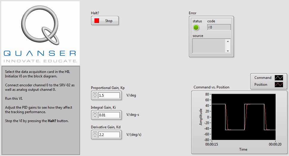
Click on the Front Panel button to stop the VI.
Copyright © Quanser Inc. This page was generated 2024-11-15. Submit feedback to Quanser about this page.
Link to this page.