
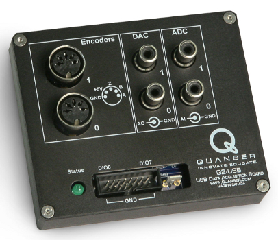
Quanser Q2-USB
The Quanser Q2-USB is an innovative, low-cost, and portable H.I.L. control board with a basic range of input and output support. A wide variety of devices with analog and digital sensors as well as quadrature encoders are easily connected to the Quanser Q2-USB. For more information, visit the website for the Quanser Q2-USB.
The RCP Toolkit driver name for this card is q2_usb.
The features of the Quanser Q2-USB are:
| USB devices are packet based, so all information is read and written in a single packet at once. To use your DAQ most efficiently, try to use just a single CL HIL Read and a single CL HIL Write VI in your diagram. |
Clocks
The Quanser Q2-USB supports a single hardware "clock", as well as one system timer. The system timer has 1ms resolution. The hardware clock is actually the USB data rate from which the diagram can base its timing. Its functionality is fixed as a hardware time base, though there are some limited configuration options in the Board-Specific Options. Theoretically, if you use the hardware time base using a HIL Read Timebase, you can achieve any timebase that is a multiple of 125us (8kHz), but realistically for most computers, the limit is 1000us (1kHz) to 500us (2kHz).
Analog Inputs
The Quanser Q2-USB supports two 12-bit single-ended analog inputs with a ±10V range. Hence analog channel numbers range from 0 to 1.
Since the range of the analog inputs is fixed at ±10V, there is no need to configure the analog input ranges on the HIL Initialize VI's Analog Inputs tab.
Analog Outputs
The Quanser Q2-USB supports two 12-bit single-ended analog outputs with a ±10V range. Hence analog channel numbers range from 0 to 1.
In order to have analog outputs set to a particular voltage when the block diagram is run or stopped, the analog outputs must be configured on the HIL Initialize VI's Analog Outputs tab.
Once the analog output ranges have been configured, set the Initial analog outputs and Final analog outputs to the desired voltages.
| Each analog output can source up to 5mA of current and maintain the specifications listed in the user manual. |
Digital I/O
The Quanser Q2-USB supports 8 bidirectional digital I/O lines. Hence digital input channel numbers range from 0 to 7. A digital I/O line cannot be used as an input and output at the same time. The LED can be controlled as digital output 8 when configured for user mode with the Board-Specific Options.
Since the digital I/O lines may be individually programmed as inputs or outputs on the Quanser Q2-USB, all the channels which will be used for digital outputs must be configured on the HIL Initialize VI's Digital I/O tab.
To set the digital output values when the block diagram is run or stopped, set the Initial digital outputs and Final digital outputs parameters to the desired values respectively.
| Each digital output can source or sink up to 4mA of current maximum at 3.3V. Do not exceed these maximums! |
Encoder Inputs
The Quanser Q2-USB supports two quadrature encoder inputs with 16-bit count values. Hence encoder channel numbers range from 0 to 1.
In order to set the encoder counters to a particular count when the VI is run, the encoder inputs must be configured on the HIL Initialize VI's Encoder Inputs tab.
The Quanser Q2-USB only supports the 4X quadrature mode. Since the Quanser Q2-USB has 16-bit counters, valid initial count values range from -32,768 to +32,676.
PWM Outputs
The Quanser Q2-USB driver supports two PWM output channels. The PWM outputs are shared with digital I/O lines 0 and 1. To change from the digital function to the PWM function, you must first set the appropriate Board-Specific Options.
These two channels are driven by independent timebases so they may operate at different frequencies and in different modes. The PWM base frequencies can range from 2.384Hz up to 40MHz. The resolution of your PWM can be as high as 16-bits or as low as 1-bit depending on the selected frequency. Use the PWM configuration wizard (the "..." button to the right of any of the active PWM fields on the PWM Outputs tab) to get more information about what resolution you will get at what frequencies.
The PWM output channels support mode 0 (duty cycle, fixed frequency), and mode 4 (active pulse time, fixed frequency). Both modes will only update after a given cycle is complete to ensure "glitchless" transitions. Therefore, for slow base frequencies, it may take several samples of your VI control loop before the update is seen on the output. RC servos for instance typically run with a period of 20ms, so a 1ms controller may need to wait up to 20 samples before the desired output is observed.
| Each PWM output can source or sink up to 4mA of current maximum at 3.3V. Do not exceed these maximums! |
Other Inputs
The Quanser Q2-USB card does not support other inputs.
Other Outputs
The Quanser Q2-USB card does not support other outputs.
Interrupts
The Quanser Q2-USB card, or its driver, does not support any interrupt sources.
Watchdog
The Quanser Q2-USB supports the watchdog functionality with a dedicated timer. The timer may be programmed with any interval between 125us and 8.1 seconds. The board is capable of resetting the analog outputs, digital outputs and PWM outputs to any state upon expiration of the watchdog timer. Resetting of the outputs occurs without software intervention, and therefore may be used as a safety mechanism in the event of software failure.
To enable the resetting of the analog or digital, check the Set output on watchdog options on the respective tabs of the HIL Initialize VI parameters dialog. Set the Output on watchdog expiry fields to the desired values. Then place a CL HIL Watchdog VI in the diagram.
Once the watchdog has expired, further output is disabled until the watchdog state is cleared. Hence, in RCP, the outputs will remain in the watchdog state even after the VI is stopped, unless a CL HIL Watchdog Clear VI is used to clear the watchdog state. Restarting the VI will automatically clear the watchdog.
Board-Specific Options
The Quanser Q2-USB has a number of board-specific options to control specialized functionality of the card. These options control the PWM configuration and the ability to change the USB communications bandwidth. You can click the browse button to the right of the Board-specific options field to bring up a dialog to configure these options. The name of the option in the dialog is shown in parentheses.
d0 (D0 mode)
This option configures line 0 of the digital I/O to digital input or output (digital) or PWM
(pwm). Note that if the line is configured as pwm, this will supersede any digital input
or output settings. By default, it is configured as a digital line.
d1 (D1 mode)
This option configures line 1 of the digital I/O to digital input or output (digital) or PWM
(pwm). Note that if the line is configured as pwm, this will supersede any digital input
or output settings. By default, it is configured as a digital line.
update_rate (Update rate)
This option is used to set the base rate for the hardware time base. The (normal) rate will
use a 1ms (1khz) base rate. Alternatively, for higher speeds and lower latencies, the fast rate can be
will use a 125us (8kHz) base rate. Your VI may use a sample period of any multiple of these base rates. Using a
1ms sample time for your VI will work with either the fast or slow option for instance, but you should get lower
latencies with the fast option. Using the fast mode will result in higher CPU utilization for the communications though.
led (LED mode)
This option is used to switch between the default DAQ controlled use (auto) of the LED (see the
Q2-USB user manual for details) or a user controlled mode (user). By default, it is configured
for the DAQ controlled use.
decimation (Decimation)
The decimation parameter is an advanced option that allows a block diagram using a hardware timebase to run multiple iterations of the control loop for each effective sampling instant. This feature can be particularly useful when combining physics models with real-time hardware access for haptic displays.
Properties
The Quanser Q2-USB card does not support any properties.
Targets
|
Target |
Supported |
Comments |
|---|---|---|
|
Yes |
Fully supported. |
See Also
Copyright © Quanser Inc. This page was generated 2024-11-15. Submit feedback to Quanser about this page.
Link to this page.

