
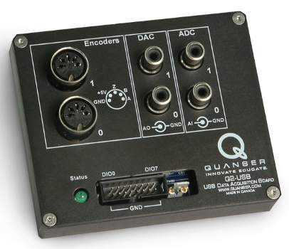
Quanser Q2-USB
The Quanser Q2-USB is an innovative, low-cost, and portable H.I.L. control board with a basic range of input and output support. A wide variety of devices with analog and digital sensors as well as quadrature encoders are easily connected to the Quanser Q2-USB. For more information, visit the website for the Quanser Q2-USB.
The features of the Quanser Q2-USB are:
| USB devices are packet based, so all information is read and written in a single packet at once. To use your DAQ most efficiently, try to use just a single HIL Read and a single HIL Write/HIL Write Timebase block in your diagram. |
The QUARC driver name for this card is q2_usb.
Clocks
The Quanser Q2-USB supports has a single hardware "clock", as well as one system timer. The system timer has 1ms resolution. The hardware clock is actually the USB data rate from which the diagram can base its timing. Its functionality is fixed as a hardware time base, though there are some limited configuration options in the Board-Specific Options. Theoretically, if you use the hardware time base using a HIL Read Timebase, you can achieve any timebase that is a multiple of 125us (8kHz), but realistically for most computers, the limit is 1000us (1kHz) to 500us (2kHz).
Analog Inputs
The Quanser Q2-USB supports two 12-bit single-ended analog inputs with a ±10V range. Hence analog channel numbers range from 0 to 1.
The range of the analog inputs is fixed at ±10V.
Analog Outputs
The Quanser Q2-USB supports two 12-bit single-ended analog outputs with a ±10V range. Hence analog channel numbers range from 0 to 1.
In order to have analog outputs set to a particular voltage when the model is loaded
or unloaded, the analog outputs must be configured on the
HIL Initialize
block's Analog Outputs
tab. Set the Analog output channels field to
all the analog output channels that will be used on the board for the current diagram.
For example, enter [0, 1] to indicate both channels 0 and 1.
Once the analog output ranges have been configured, set the Initial analog outputs and Final analog outputs to the desired voltages. If the vectors specified in these fields are shorter than the channel vector, the value of the last element in the vector will be used for the rest of the channels. Hence, a scalar value will apply to all channels specified in the Analog output channels field.
To set the analog output values when the watchdog expires, set the Analog outputs on watchdog expiry to the desired values matching the channel assignments on the Analog output channels.
| Each analog output can source up to 5mA of current and maintain the specifications listed in the user manual. |
Digital Inputs
The Quanser Q2-USB supports 8 bidirectional digital I/O lines. Hence digital input channel numbers range from 0 to 7. A digital I/O line cannot be used as an input and output at the same time.
Since the digital I/O lines may be individually programmed as inputs or
outputs on the Quanser Q2-USB, all of those 8 channels which will be used
for digital inputs should be configured on the HIL Initialize
block's Digital Inputs tab. Set the Digital input channels field to all
the digital I/O channels that will be used as digital inputs on the board for the current diagram. For example, enter
3:7 to designate channels 3 through 7 as digital inputs. Specify
[0, 4, 5] to indicate that channels 0, 4 and 5 are to be configured
as digital inputs.
Digital Outputs
The Quanser Q2-USB supports 8 bidirectional digital I/O lines and 1 LED. Hence digital output channel numbers range from 0 to 8. A digital I/O line cannot be used as an input and output at the same time. The LED can be controlled as digital output 8 when configured for user mode with the Board-Specific Options.
Since the digital I/O lines may be individually programmed as inputs or outputs
on the Quanser Q2-USB, all the channels which will be used for digital outputs must be configured
on the HIL Initialize block's
Digital Outputs tab. Set the Digital output channels
field to all the digital I/O channels that will
be used as digital outputs on the board for the current diagram. For example, enter
3:7 to designate channels 3 through 7 as digital outputs. Specify
[0, 4, 5] to indicate that channels 0, 4 and 5 are to be configured
as digital outputs.
| If you do not enter the number into the Digital output channels, the card will default to inputs. However, this will not prevent a HIL Write block from writing to those digital outputs. This can be used to preinitialize the outputs if you switch from digital input to digital output at a later point in time. |
To set the digital output values when the model is loaded or unloaded, set the Initial digital outputs and Final digital outputs parameters to the desired values respectively. If the vectors specified in these fields are shorter than the channel vector, the value of the last element in the vector will be used for the rest of the channels. Hence, a scalar value will apply to all channels specified in the Digital output channels field.
To set the digital output values when the watchdog expires, set the Digital outputs on watchdog expiry to states to match the channel assignments in the Digital output channels field. States 0 (low), 1 (high), and 3 (leave at the current state) are supported by the Quanser Q2-USB.
| Each digital output can source or sink up to 4mA of current maximum at 3.3V. Do not exceed these maximums! |
Encoder Inputs
The Quanser Q2-USB supports two quadrature encoder inputs with 16-bit count values. Hence encoder channel numbers range from 0 to 1.
In order to set the encoder counters to a particular count when the model is loaded, the encoder inputs must
be configured on the HIL Initialize
block's Encoder Inputs tab. Set the Encoder input channels
field to all the encoder channels that will be
used on the board for the current diagram. For example, enter [0, 1] specify both channels.
The Quanser Q2-USB only supports the 4X quadrature mode. If the vectors specified in these fields are shorter than the channel vector, the value of the last element in the vector will be used for the rest of the channels. Hence, a scalar value will apply to all channels specified in the Encoder input channels field. Since the Quanser Q2-USB has 16-bit counters, valid initial count values range from -32,768 to +32,767.
PWM Outputs
The Quanser Q2-USB driver supports two PWM output channels. The PWM outputs are shared with digital I/O lines 0 and 1. To change from digital function to PWM function, you must first set the appropriate Board-Specific Options.
These two channels are driven by independent timebases so they may operate at different frequencies and in different modes. The PWM base frequencies can range from 2.384Hz up to 40MHz. The resolution of your PWM can be as high as 16-bits or as low as 1-bit depending on the selected frequency. Use the PWM configuration wizard (the "..." button to the right of any of the active PWM fields on the PWM Outputs tab) to get more information about what resolution you will get at what frequencies.
The PWM output channels support mode 0 (duty cycle, fixed frequency), and mode 4 (active pulse time, fixed frequency). Both modes will only update after a given cycle is complete to ensure "glitchless" transitions. Therefore, for slow base frequencies, it may take several samples of your model before the update is seen on the output. RC servos for instance typically run with a period of 20ms, so a 1ms controller may need to wait up to 20 samples before the desired output is observed.
To set the PWM output values when the watchdog expires, set the PWM outputs on watchdog expiry to states to match the channel assignments in the PWM output channels field.
| Each PWM output can source or sink up to 4mA of current maximum at 3.3V. Do not exceed these maximums! |
Other Inputs
The Quanser Q2-USB card does not support other inputs.
Other Outputs
The Quanser Q2-USB card does not support other outputs.
Interrupts
The Quanser Q2-USB card, or its driver, does not support any interrupt sources.
Watchdog
The Quanser Q2-USB supports the watchdog functionality with a dedicated timer. The timer may be programmed with any interval between 125us and 8.1 seconds. The board is capable of resetting the analog outputs, digital outputs and PWM outputs to any state upon expiration of the watchdog timer. Resetting of the outputs occurs without software intervention, and therefore may be used as a safety mechanism in the event of software failure.
To enable the resetting of the analog, digital or PWM outputs, check the Set analog outputs at watchdog expiration, Set digital outputs on watchdog expiration or Set PWM outputs on watchdog expiration options in the HIL Initialize block parameters. Set the analog, digital and PWM output values on watchdog expiration to the desired values. Then place a HIL Watchdog block in the diagram.
Once the watchdog has expired, further output is disabled until the watchdog state is cleared. Hence, in Simulink models, the outputs will remain in the watchdog state even after the model is stopped, unless a HIL Watchdog Clear block is used to clear the watchdog state. Restarting the model will automatically clear the watchdog.
Board-Specific Options
The Quanser Q2-USB has a number of board-specific options to control specialized functionality of the card. These options control the PWM configuration and the ability to change the USB communications bandwidth.
In the HIL Initialize block, click the "..." button to the right of the Board-specific options field to bring up a graphical configuration of these options.
d0
This option configures line 0 of the digital I/O to digital input or output (digital) or PWM
(pwm). Note that if the line is configured as pwm, this will supersede any digital input
or output settings. By default, it is configured as a digital line.
d1
This option configures line 1 of the digital I/O to digital input or output (digital) or PWM
(pwm). Note that if the line is configured as pwm, this will supersede any digital input
or output settings. By default, it is configured as a digital line.
update_rate
This option is used to set the base rate for the hardware time base. The (normal) rate will
use a 1ms (1khz) base rate. Alternatively, for higher speeds and lower latencies, the fast rate can be
will use a 125us (8kHz) base rate. Your model may use a sample period of any multiple of these base rates. Using a
1ms sample rate for your model will work with either the fast or slow option for instance, but you should get lower
latencies with the fast option. Using the fast mode will result in higher CPU utilization for the communications though.
|
It is recommended to use ( |
led
This option is used to switch between the default DAQ controlled use (auto) of the LED (see the
Q2-USB user manual for details) or a user controlled mode (user). By default, it is configured
for the DAQ controlled use.
decimation
Defaults to 1. This is an advanced feature that is designed to allow your diagram to execute multiple times for each sample of the hardware timebase. At a decimation of 10 for instance, the DAQ will only read and write once every 10 samples. A typical scenario is that you want to run a simulation of your physical system at a higher resolution than your sample rate (particularly with a slower DAQ). Assume your DAQ is capable of a maximum of 1kHz, but you require the model to be simulated at 10kHz. Set your sample time to 10kHz and the decimation option in the HIL Initialize to 10 and place a HIL Read Timebase block in your diagram. When the model is executed, the first sample will read and write to the DAQ. The next 9 samples will be executed as quickly as possible (the integrators will assume the correct period of time has passed, but in real-time these steps will be as fast as they can execute). Data from read blocks will be repeated, and write and set blocks will be ignored. The 11th sample will now wait on the hardware timebase, resynchronizing the diagram to real-time. When the hardware timebase occurs, new data will be sampled by the read blocks and the current outputs will be output by the write blocks.
Since this feature affects everything in the diagram, other features which assume synchronization with real-time may also need to be decimated.
Properties
The Quanser Q2-USB card does not support any properties.
Targets
|
Target |
Supported |
Comments |
|---|---|---|
|
Yes |
Fully supported. |
|
|
Yes |
Fully supported. |
|
|
Yes* |
Support for this target is in beta. If you are using it, we would appreciate any feedback. |
|
|
No |
Not supported. |
|
|
No |
Not supported. |
|
|
No |
Not supported. |
|
|
Yes* |
Support for this target is in beta. If you are using it, we would appreciate any feedback. |
|
|
No |
Not supported. |
|
|
No |
Not supported. |
|
|
No |
Not supported. |
|
|
No |
Not supported. |
|
|
No |
Not supported. |
|
|
No |
Not supported. |
|
|
No |
Not supported. |
|
|
No |
Not supported. |
|
|
Rapid Simulation (RSIM) Target |
Yes |
Supported with no communication to the hardware. |
|
Normal simulation |
Yes |
Supported with no communication to the hardware. |
See Also
Copyright ©2026 Quanser Inc. This page was generated 2026-05-13. Submit feedback to Quanser about this page.
Link to this page.

