
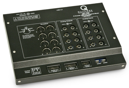
Quanser Q8-USB
The Quanser Q8-USB is an innovative H.I.L. control board with an extensive range of input and output support. A wide variety of devices with analog and digital sensors as well as quadrature encoders are easily connected to the Quanser Q8-USB. This USB solution is ideal for use in control systems and complex measurement applications. For more information, visit the Quanser website for the Quanser Q8-USB.
The QUARC driver name for this card is q8_usb .
The features of the Quanser Q8-USB are:
This USB system enables you to turn your PC into a powerful Desktop Control Station.
Clocks
The Quanser Q8-USB supports three hardware clocks, HARDWARE_CLOCK_0 (0), HARDWARE_CLOCK_1 (1) and HARDWARE_CLOCK_2 (2). The first clock is generally used as a hardware timebase using one of the HIL Timebase blocks. The HARDWARE_CLOCK_0 clock may be used to generate timebases up to 1 kHz when the normal update rate is selected in the board-specific options, or up to 8 kHz when the fast update rate is selected.
The HARDWARE_CLOCK_1 clock allows the external input (EXT_INT) line to be used as a hardware timebase. This feature can be useful for synchronizing to a video synchronization signal, for example.
The HARDWARE_CLOCK_2 clock allows the A/D conversion (CONVERT) line to be used as a hardware timebase. This feature can be used for synchronizing A/D conversions on multiple cards.
Analog Inputs
The Quanser Q8-USB supports eight 16-bit differential analog inputs with a ±10V range. Hence analog channel numbers range from 0 to 7.
The range of the analog inputs may be configured as ±5V or ±10V via the HIL Initialize block's Analog Inputs tab.
The analog inputs measured using a single HIL Read block will be sampled simultaneously. All eight analog inputs may be sampled simultaneously by reading all eight channels with a single HIL Read block.
Analog Outputs
The Quanser Q8-USB supports eight 16-bit single-ended analog outputs with a programmable range. As there are eight outputs, analog channel numbers range from 0 to 7.
In order to have analog outputs set to a particular voltage when the model is loaded
or unloaded, the analog outputs must be configured on the
HIL Initialize
block's Analog Outputs
tab. Set the Analog output channels field to
all the analog output channels that will be used on the board for the current diagram.
For example, enter 1:3 to indicate channels 1 through 3. Specify
[0, 2, 7]
to indicate channels 0, 2 and 7.
Set the Analog output maximums and the Analog output minimums field to the
appropriate values for the desired analog output ranges. Valid ranges are
0-5V, 0-10V, 0-10.8V, ±5V, ±10V and ±10.8V
.
| Note that the analog inputs are restricted to a ±10V range, so do not connect the analog outputs to the analog inputs if the analog outputs are configured for the ±10.8V range. |
Once the analog output ranges have been configured, set the Initial analog outputs and Final analog outputs to the desired voltages.
If the vectors specified in these fields are shorter than the channel vector, the value of the last element in the vector will be used for the rest of the channels. Hence, a scalar value will apply to all channels specified in the Analog output channels field.
Digital Inputs
The Quanser Q8-USB supports 8 digital input lines and two special digital input lines. Hence digital input channel numbers range from 0 to 9. Channels 8 and 9 are EXT_INT and CONVERT respectively. Digital inputs cannot be reprogrammed as digital outputs.
The EXT_INT input reads the value of the external interrupt pin on the Control header of the Quanser Q8-USB terminal board.
The CONVERT input reads the value of the A/D Convert pin on the Control header of the Quanser Q8-USB terminal board.
Digital inputs 0-7 are sampled simultaneously when measured using a single HIL Read block. The first 8 digital inputs may be sampled simultaneously by reading all 8 channels with a single HIL Read block.
Digital Outputs
The Quanser Q8-USB supports 8 digital output lines. Individual lines may be configured as PWM outputs via the board-specific options.
All the channels which will be used for digital outputs should be configured
on the HIL Initialize block's
Digital Outputs tab. Set the Digital output channels
field to all the digital output channels that will
be used as digital outputs on the board for the current diagram. For example, enter
3:7 to designate channels 3 through 7 as digital outputs. Specify
[0, 4, 5] to indicate that channels 0, 4 and 5 are to be used
as digital outputs.
To set the digital output values when the model is loaded or unloaded, set the Initial digital outputs and Final digital outputs parameters to the desired values respectively. If the vectors specified in these fields are shorter than the channel vector, the value of the last element in the vector will be used for the rest of the channels. Hence, a scalar value will apply to all channels specified in the Digital output channels field.
| Each digital output can source up to 5mA of current maximum, with a total of 75mA maximum. Do not exceed these maximums! |
Digital outputs 0-7 are updated simultaneously when written using a single HIL Write block. All 8 digital outputs may be updated simultaneously by writing all 8 channels with a single HIL Write block.
Encoder Inputs
The Quanser Q8-USB supports eight quadrature encoder inputs with 24-bit count values. Hence encoder channel numbers range from 0 to 7.
In order to set the encoder counters to a particular count or to change the default
quadrature or filtering when the model is loaded, the encoder inputs must
be configured on the HIL Initialize
block's Encoder Inputs tab. Set the Encoder input channels
field to all the encoder channels that will be
used on the board for the current diagram. For example, enter
2:7
to
indicate channels 3 through 7 are used as encoder inputs. Specify
[0, 2, 7]
to indicate that channels 0, 2 and 7 are used as encoder inputs.
The Quanser Q8-USB supports non-quadrature (count and direction) and 4X quadrature. Filtering may be turned on or off. Since the Quanser Q8-USB has 24-bit counters, valid initial count values range from -8,388,608 to +8,388,607.
If the vectors specified in these fields are shorter than the channel vector, the value of the last element in the vector will be used for the rest of the channels. Hence, a scalar value will apply to all channels specified in the Encoder input channels field.
Sampling of the encoders is always synchronized with A/D conversions.
The direction of any encoder channel may be reversed via the board-specific enc<n>_dir
options. The ability to reverse the direction in which the encoder counts is convenient when connecting
to hardware because it obviates the need for confusing sign changes in code.
The Quanser Q8-USB also supports measurement of the encoder velocities in hardware. The encoder velocity measurements provide velocity information with no differentiation required. The velocities generally have higher resolution than those obtained by differentiation, particularly at slow velocities, and can provide instantaneous velocities. Refer to the "other input channels" below for more details!
| Note that the Quanser Q8-USB provides encoder velocities based on the rising edge of the A signal only. The measurements are therefore 1X quadrature, not full, 4X, quadrature. The velocities measured are very accurate but may have phase delays that are velocity dependent due to the lack of full quadrature support. |
The Quanser Q8-USB provides support for the index pulse on each encoder channel. The encoder count values when the last index pulses occurred are available as additional outputs. Refer to "output input channels" below for details.
The encoder counters may also be programmed to reload from the initial value when an index pulse
occurs. Set the appropriate enc<n>_reload flag in the board-specific options to enable
this feature. However, for control purposes, it is probably better to look for changes in the most recent
index position as reported by the other input channels than to have the actual encoder counts change
asynchronously with respect to the software.
The index pulse is detected when the A, B and Z signals of the encoder have a particular polarity. The polarity of each of these signals used to detect an index pulse is programmed through the board-specific options (see below). Doing so typically allows the index position to be determined with full quadrature accuracy. If the other input channels reflecting the position of the last index pulse continuously change as the encoder is rotated then the polarity of Z is likely incorrect.
Encoder inputs are sampled simultaneously when measured using a single HIL Read block. All eight encoder inputs may be sampled simultaneously by reading all eight channels with a single HIL Read block.
Furthermore, the encoder positions, index positions and velocities are all sampled together simultaneously (in hardware) when measured using a single HIL Read block. This functionality is very useful for complex mechanical devices in which it is important to know the joint angles and velocities at a particular instant in time because small errors in these quantities could lead to inaccurate kinematic calculations. Without simultaneous sampling the mechanical system could not be guaranteed to be in exactly the same position when the different joint angles and velocities were measured.
| The HIL Set Encoder Counts block and hil_set_encoder_counts function may result in increased sampling period jitter at fast rates, and possibly even a lost sampling instant. Since setting of the encoder counts is generally only done once (after a calibration sequence, for example), this additional jitter is not generally an issue, but users should be cognizant of its effect. |
PWM Outputs
The Quanser Q8-USB driver supports up to eight PWM output channels. The PWM outputs share the same pins as the digital outputs. The function of each pin is determined by the board-specific options (see Board-Specific Options below).
These eight channels are all driven by one timebase, but their duty cycles may be independently controlled. It is possible to synchronize the execution of a model to this PWM timebase by using it as a hardware timebase. Refer to the section on Clocks above.
The PWM output channels support a broad variety of options and are extremely flexible. They are suitable for a number of applications, including more specialized applications such as three-phase motor control, driving RC servos, H-bridges and inverters, pulse generation and more.
Each output channel can be programmed with a duty cycle ranging from 0 to 100% inclusive. Since the outputs can be set to be fully low (0%) or high (100%), they can also serve as additional digital outputs if necessary.
The output pulse may be aligned at the beginning of the PWM period (leading alignment), center of the PWM period (center alignment) or at the end of the PWM period (trailing alignment).
Channels can be coordinated so that the output pulses of pairs of channels are synchronized or complementary. Most importantly, independent leading and trailing edge deadband may be inserted between the coordinated outputs so that H-bridges may be driven without large current spikes.
PWM outputs can be configured in "one-shot" mode, which allows greater resolution when driving RC servos. In one-shot mode, the PWM output pulses only occur once each time the PWM outputs are written. Hence, PWM output pulses may be generated less frequently, while still maintaining high resolution in the width of the duty cycle.
This mode is particularly well suited for RC servos, where the time between pulses is long but the width of the pulse is much narrower. For example, RC servos typically require a pulse every 20ms. However, the pulse width itself may vary only between 1ms and 2ms to get the full-scale range of the RC servo. Using a PWM period of 20ms would waste much of the resolution of the PWM output on the 18ms of the period that are never used. One-shot mode, however, allows a PWM period of 2ms to be employed so that more of the resolution of the PWM output is available to produce the 1ms to 2ms pulse. An independent timebase may then be used to generate the 20ms period.
The PWM outputs also support an encoder emulation mode. In the encoder emulation mode paired or complementary outputs may be configured to emulate the A and B channels of a quadrature encoder. The input to the HIL PWM Output block or hil_write_pwm_outputs function in this case is the desired velocity expressed in counts per second.
For a complete description of all the options available, including diagrams, refer to PWM Output Configurations.
The PWM outputs are updated simultaneously when written using a single HIL Write block. All eight PWM outputs may be updated simultaneously by writing all 8 channels with a single HIL Write block.
Other Inputs
The Quanser Q8-USB supports 14 other input channels. Other input channel numbers are assigned according to functionality rather than sequentially in QUARC, so that boards from more than one manufacturer still use the same other input channel numbers for the same functionality. This scheme makes it easier to exchange boards from different manufacturers. Refer to QUARC Other Channels for a list of the Other Input or Output channel number ranges defined for any HIL Data Acquisition Card and their SI units.
Other input channels 13000 through 13007 reflect the positions of the most recently encountered encoder index pulses for encoder inputs 0 through 7 respectively. The values are in counts. These inputs are useful for determining where the index positions are located on the encoders.
Other input channels 14000 through 14007 are hardware velocity measurements for encoder inputs 0 through 7 respectively, in counts per second. These measurements are independent of the sample rate of the model and are unaffected by sample rate jitter. They reflect the instantaneous velocity of the encoder channel.
The fastest resolvable velocity is almost 100 million counts per second (without filtering). The slowest measurable velocity (besides zero) is approximately 6 counts per second.
The channels related to the encoders are all sampled simultaneously when measured using a single HIL Read block.
Other Outputs
The Quanser Q8-USB card does not support other outputs.
Interrupts
External interrupt (EXT_INT) interrupt
This interrupt is generated when a rising or falling edge appears on the EXT_INT pin on the Control header. The falling edge is used to trigger an interrupt by default, but the polarity may be changed using the ext_int_polarity board-specific option. Use interrupt channel 0 to respond to this interrupt.
A/D conversion trigger (CONVERT) interrupt
This interrupt is generated when a rising or falling edge appears on the CONVERT pin on the Control header. The rising edge is used to trigger an interrupt by default, but the polarity may be changed using the convert_polarity board-specific option. Use interrupt channel 1 to respond to this interrupt.
Encoder index pulse interrupts
Each encoder channel is capable of generating an interrupt when the index pulse is seen. There is a separate interrupt for each encoder channel. The polarity of the A, B and Z signals required to recognize an index pulse may be configured via the enc0_a, enc0_b, enc0_z and similar board-specific options. Use interrupt channels 1000-1007 to respond to these interrupts for encoder channels 0-7 respectively.
Watchdog
The Quanser Q8-USB supports a watchdog timer. The timer may be programmed with any interval from 125 microseconds and upward. The board is capable of resetting the analog outputs, digital outputs and PWM outputs to any state upon expiration of the watchdog timer. Resetting of the outputs occurs without software intervention, and therefore may be used as a safety mechanism in the event of software failure.
To enable the resetting of the analog, digital or PWM outputs, check the Set analog outputs at watchdog expiration, Set digital outputs on watchdog expiration or Set PWM outputs on watchdog expiration options in the HIL Initialize block parameters. Set the analog, digital and PWM output values on watchdog expiration to the desired values. Then place a HIL Watchdog block in the diagram.
When the watchdog functionality is used, the WATCHDOG pin will reflect the status of the
watchdog timer. The WATCHDOG pin may be found on the CONTROL header on the Quanser Q8-USB terminal
board. This pin is normally high. If the watchdog timer is allowed to
expire, then this pin will go low.
Once the watchdog has expired, further I/O is disabled until the watchdog state is cleared or the watchdog timer is stopped. The watchdog pin remains low after expiration until the watchdog is restarted.
Hence, in Simulink models, the WATCHDOG pin will remain low after watchdog
expiration even after the model is stopped, unless a HIL Watchdog Clear
block is used to clear the watchdog state. Restarting the model causes the WATCHDOG pin to go
high once more. These semantics make the WATCHDOG pin useful for ensuring product safety.
Board-Specific Options
The Quanser Q8-USB has a number of board-specific options to control specialized functionality of the card. These options control the polarity of certain inputs to the card, determine the watchdog and general-purpose counter functionality, and configure the PWM output semantics.
enc0_dir
Set this option to "yes", "y" or "1" to reverse the direction of encoder 0. This feature makes it easier to migrate to the Quanser Q8-USB hardware from another data acquisition card. It also allows models to be more portable to other cards.
Similar options exist for the other encoder channels e.g. enc1_dir, enc2_dir, etc.
enc0_filter
Set this option to "yes", "y" or "1" to enable filtering on encoder channel 0. The Quanser Q8-USB filtering oversamples the A, B and Z channels are tries to eliminate spurious glitches in the inputs. However, use of filtering slows down the maximum encoder velocity that may be measured.
Similar options exist for the other encoder channels e.g. enc1_filter, enc2_filter, etc.
enc0_a
This option determine the state of the A signal required for an index pulse to be recognized. Set this option to "yes", "y" or "1" to require that the A signal be low for an index pulse to be detected. Set it to "no", "n" or "0" to require the A signal to be high.
Similar options exist for the other encoder channels e.g. enc1_a, enc2_a, etc.
enc0_b
This option determine the state of the B signal required for an index pulse to be recognized. Set this option to "yes", "y" or "1" to require that the B signal be low for an index pulse to be detected. Set it to "no", "n" or "0" to require the B signal to be high.
Similar options exist for the other encoder channels e.g. enc1_b, enc2_b, etc.
enc0_z
This option determine the state of the Z signal required for an index pulse to be recognized. Set this option to "yes", "y" or "1" to require that the Z signal be low for an index pulse to be detected. Set it to "no", "n" or "0" to require the Z signal to be high.
Similar options exist for the other encoder channels e.g. enc1_z, enc2_z, etc.
| If this option is set incorrectly then an index pulse is detected every time the A and B signals match the criteria defined by the enc0_a and enc0_b options - which is basically "all" the time. If the index position vary seemingly continuously, try changing this option to the opposite polarity. |
enc0_reload
Set this option to "yes", "y" or "1" to reload encoder counter 0 when the index pulse occurs. This option is generally not recommended because it wreaks havoc on controllers if the controller is not carefully designed. The Quanser Q8-USB keeps track of the last position at which an index pulse occurred in a separate set of registers, so reloading the encoder counter on an index pulse is less important.
Similar options exist for the other encoder channels e.g. enc1_reload, enc2_reload, etc.
enc0_velocity
Set this option to the minimum velocity in counts per second that should be detected by the encoder velocity hardware. This limit is an artificial limit that is useful when friction stops the device long before it reaches the slowest detectable velocity of the Quanser Q8-USB hardware. If this option is set to zero then the slowest velocity measurable by the hardware is used.
Similar options exist for the other encoder channels e.g. enc1_velocity, enc2_velocity, etc.
pwm0_en
This option enables PWM output 0. The PWM output will appear on the pin normally used for digital output 0.
Similar options exist for the other PWM channels e.g. pwm1_en, pwm2_en, etc.
pwm_immediate
Set this option to "yes", "y" or "1" to update PWM outputs as soon as a value is written to one of the PWM channels. Normally, the changes in the duty cycle of the PWM outputs are synchronized to the beginning of the PWM period to avoid glitches in the PWM outputs. Setting this option to "yes" causes the outputs to be updated immediately, even if it means producing a second pulse within the same PWM period. For example, when using trailing edge alignment, switching from a 90% duty cycle to a 10% duty cycle near the middle of the PWM period could cause the 90% duty cycle to be truncated immediately and then restarted near the end of the PWM period to generate the 10% duty cycle pulse. Some systems, however, do perform better when the PWM outputs are updated immediately, so this option is provided.
convert_polarity
Set this option to "yes", "y" or "1" to make the CONVERT line trigger on a rising edge. Set it to "no", "n" or "0" to configure the CONVERT line to trigger on a falling edge. It triggers on the rising edge by default. This option does not affect the polarity of the CONVERT line when it is read as a simple digital input.
use_convert
Set this option to "yes", "y" or "1" to cause the board's inputs to only be sampled when a rising or falling edge occurs on the CONVERT input (according to the convert_polarity option). This feature allows the inputs to be sampled based on an external trigger rather than at regular intervals. Setting this option does not cause the CONVERT line to be used for hardware timebases - it only affects when the inputs to the board are actually sampled.
update_rate
Set this option to either "normal" or "fast". At the normal update rate the Quanser Q8-USB card can operate at speeds up to 1 kHz, although 500 Hz is recommended. At the fast update rate it can operate at speeds up to 8 kHz, although this mode is typically used for 1 kHz operation. The fast update rate uses significantly more CPU time and is not recommended unless the extra speed is required.
ext_int_polarity
Set this option to "yes", "y" or "1" to make the EXT_INT line trigger on the rising edge. Set it to "no", "n" or "0" to configure the EXT_INT line to trigger on the falling edge. It triggers on the falling edge by default. This option does not affect the polarity of the EXT_INT line when it is read as a simple digital input.
ext_int_watchdog
Set this option to "yes", "y" or "1" to activate the EXT_INT line as an external watchdog input. When a rising or falling edge (according to the ext_int_polarity option) occurs on the EXT_INT line then the board enters the watchdog state and all outputs are set to their watchdog expiration states (if configured).
watchdog_polarity
Set this option to "yes", "y" or "1" to make the WATCHDOG output active-high. Set it to "no", "n" or "0" to configure the WATCHDOG output active-low. The default is active-low. The WATCHDOG output is asserted when the watchdog timer is allowed to expire. It can be used to shut down external hardware in the event that the watchdog timer expires due to a software failure.
ch0_mode
This option selects the mode for analog output 0. Seven modes are supported.
|
Mode |
Name |
Description |
|---|---|---|
|
0 |
Voltage mode |
Values written to analog outputs are strictly voltages. No closed-loop control is performed. |
|
1 |
Current mode #2 |
Values written to analog outputs are currents. Closed-loop control is performed between the analog input and analog output using a discrete-time, 32-bit fixed-point, second-order controller with feed-forward. |
|
2 |
Current mode #1 |
Values written to analog outputs are currents. Closed-loop control is performed between the analog input and analog output using a discrete-time, 32-bit fixed-point, first-order controller with feed-forward. |
|
3 |
Current mode #0 |
Values written to analog outputs are currents. Closed-loop control is performed between the analog input and analog output using a discrete-time, 32-bit fixed-point, proportional controller with feed-forward. |
|
4 |
Control mode #2 |
Values written to analog outputs are setpoints. Closed-loop control is performed between the encoder input and analog output using a discrete-time, 32-bit fixed-point, second-order controller with feed-forward. |
|
5 |
Control mode #1 |
Values written to analog outputs are setpoints. Closed-loop control is performed between the encoder input and analog output using a discrete-time, 32-bit fixed-point, proportional controller with feed-forward. |
|
6 |
Control mode #0 |
Values written to analog outputs are setpoints. Closed-loop control is performed between the encoder input and analog output using a discrete-time, 32-bit fixed-point, proportional controller with feed-forward. |
Similar options exist for the other analog output channels e.g. ch1_mode, ch2_mode, etc.
ch0_kff
This option provides the value of the feedforward term for closed-loop control on channel 0.
Similar options exist for the other PWM channels e.g. ch1_kff, ch2_kff, etc.
ch0_a0
This option provides the value of the z0 coefficient in the numerator of the closed-loop control on channel 0.
Similar options exist for the other PWM channels e.g. ch1_a0, ch2_a0, etc.
ch0_a1
This option provides the value of the z1 coefficient in the numerator of the closed-loop control on channel 0.
Similar options exist for the other PWM channels e.g. ch1_a1, ch2_a1, etc.
ch0_a2
This option provides the value of the z2 coefficient in the numerator of the closed-loop control on channel 0.
Similar options exist for the other PWM channels e.g. ch1_a2, ch2_a2, etc.
ch0_b0
This option provides the value of the z0 coefficient in the denominator of the closed-loop control on channel 0.
Similar options exist for the other PWM channels e.g. ch1_b0, ch2_b0, etc.
ch0_b1
This option provides the value of the z1 coefficient in the denominator of the closed-loop control on channel 0.
Similar options exist for the other PWM channels e.g. ch1_b1, ch2_b1, etc.
ch0_post
This option provides the value of the post-scale factor in the closed-loop control on channel 0.
Similar options exist for the other PWM channels e.g. ch1_post, ch2_post, etc.
decimation
Defaults to 1. This is an advanced feature that is designed to allow your diagram to execute multiple times for each sample of the hardware timebase. At a decimation of 10 for instance, the DAQ will only read and write once every 10 samples. A typical scenario is that you want to run a simulation of your physical system at a higher resolution than your sample rate (particularly with a slower DAQ). Assume your DAQ is capable of a maximum of 1kHz, but you require the model to be simulated at 10kHz. Set your sample time to 10kHz and the decimation option in the HIL Initialize to 10 and place a HIL Read Timebase block in your diagram. When the model is executed, the first sample will read and write to the DAQ. The next 9 samples will be executed as quickly as possible (the integrators will assume the correct period of time has passed, but in real-time these steps will be as fast as they can execute). Data from read blocks will be repeated, and write and set blocks will be ignored. The 11th sample will now wait on the hardware timebase, resynchronizing the diagram to real-time. When the hardware timebase occurs, new data will be sampled by the read blocks and the current outputs will be output by the write blocks.
Since this feature affects everything in the diagram, other features which assume synchronization with real-time may also need to be decimated.
Properties
The Quanser Q8-USB driver currently supports the following read-only properties:
|
Property |
Type |
Description |
|---|---|---|
|
PROPERTY_INTEGER_VENDOR_ID |
Integer |
USB vendor ID |
|
PROPERTY_INTEGER_PRODUCT_ID |
Integer |
USB product ID |
|
PROPERTY_STRING_MANUFACTURER |
String |
Manufacturer name |
|
PROPERTY_STRING_PRODUCT_NAME |
String |
Product name |
|
PROPERTY_STRING_MODEL_NAME |
String |
Model name |
Targets
|
Target |
Supported |
Comments |
|---|---|---|
|
Yes |
Fully supported. |
|
|
Yes |
Fully supported. |
|
|
No |
Not supported. |
|
|
No |
Not supported. |
|
|
No |
Not supported. |
|
|
No |
Not supported. |
|
|
No |
Not supported. |
|
|
No |
Not supported. |
|
|
No |
Not supported. |
|
|
No |
Not supported. |
|
|
No |
Not supported. |
|
|
No |
Not supported. |
|
|
No |
Not supported. |
|
|
No |
Not supported. |
|
|
No |
Not supported. |
|
|
Rapid Simulation (RSIM) Target |
Yes |
Supported with no communication to the hardware. |
|
Normal simulation |
Yes |
Supported with no communication to the hardware. |
See Also
Copyright ©2026 Quanser Inc. This page was generated 2026-05-13. Submit feedback to Quanser about this page.
Link to this page.
