Visualization Initialize
Adds a visualization window to your model and sets the scene parameters and content.
Library
QUARC Targets/User Interface/Visualization MATLAB Command Line Click to copy the following command line to the clipboard. Then paste it in the MATLAB Command Window: qc_open_library('quarc_library/User Interface/Visualization')
Description
The Visualization Initialize block has two primary roles. The user interface of the Visualization Initialize block is primarily used to generate a scene file which defines what meshes and textures will be used to compose the visualization and how they interrelate. The underlying function of the Visualization Initialize block is to act as a communications server. It collects all the data from the various Set Variables blocks in the model and sends it to all the connected viewers via the selected protocol.
 As you create a hierarchical structure with parent-child relationships, the actor list will arrange itself into a
tree structure. Clicking on an actor with a "+" next to it while holding down the Alt key will expand the tree. The "+" and "-" buttons at the
bottom will expand or collapse the entire tree. Double-clicking on an actor will allow the actor to be edited.
As you create a hierarchical structure with parent-child relationships, the actor list will arrange itself into a
tree structure. Clicking on an actor with a "+" next to it while holding down the Alt key will expand the tree. The "+" and "-" buttons at the
bottom will expand or collapse the entire tree. Double-clicking on an actor will allow the actor to be edited.
Input Ports
This block has no input ports.
Output Ports
This block has no output ports.
Parameters and Dialog Box
Common Buttons
The dialog box for the Visualization Initialize block contains the usual , , and buttons for agreeing to the changes and closing the dialog, canceling the changes, applying the current changes, and getting help respectively. It also contains an additional button called . The button is used to preview your scene and allow you to visually set the initial position, rotation, scale, and color of each actor. The details of this button are covered in the Visualization Animate Dialog page. Changes will not be made to the scene file until or are clicked. Note, you must close all Visualization Set Variables dialogs before applying any changes to the scene.
Go to other blocks using this visualization
Opens a dialog that lists all the Visualization blocks in the model which are currently using the same reference selected in the Visualization reference parameter. The dialog may be used to go to another Visualization block in the model just by double-clicking on the name of the block in the dialog box.
Individual Panes
Main Pane
The Main pane of the dialog appears as follows:
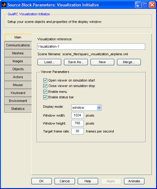
Visualization reference
This is the name assigned to the visualization. The name will show up in the list of visualization references, and underneath all the Set Variables blocks. It is this name that associates the Set Variables blocks with this particular animation server. When a Set Variables block is added to a model, it will automatically associate itself with the first Visualization Initialize block that was added to the model.
Scene Filename
The user interface of the Visualization Initialize block is primarily used to generate an xml scene file. Before a model with a visualization can be used, you must specify a filename for the scene file. This can be done by using an existing scene file by clicking the button and navigating to the appropriate file, or clicking the button to create a new file. Note, if you use to create a new file, the filename shown in the Scene Filename will be appended with "(unsaved)" until you click at which point the file will be written. After that, the selected file will be updated with modifications whenever you click or .
If you are currently working on a scene, but wish to create a new scene, then click the button to reset the interface to the defaults. The scene file will also become reset to untitled, so you will need to click to create a new file. If you mistakenly clicked , then use the button to reload your previous scene.
Finally, if you would like to add elements to your present scene from other scenes you can use the button. Mesh, image, and object resources will be consolidated where possible, but Actors will be duplicated. In the case of merging a scene with itself, there will be two copies of every actor from the original scene. There can only be one camera in the scene, so children of the camera in the merged scene will become children of the camera in the existing scene. The parent of the camera in the current scene will not be changed. If the camera in the merged scene is the child of another object, the camera will simple be removed and its parents will be left intact. A number of premade assemblies are included in the $(QUARC_DIR)/resources/scene_files MATLAB Command Line Click to copy the following command line to the clipboard. Then paste it in the MATLAB Command Window: dos(sprintf('explorer.exe "%s" &', fullfile(qc_root, 'resources', 'scene_files'))); folder to help you quickly put preassembled elements into your scenes.
Open viewer on simulation start (tunable offline)
Automatically opens the visualization viewer when a normal simulation is started, or you connect to an external model. If this option is not checked, you can manually open the viewer from the start menu and manually connect. If the model is running on the same machine as your visualization, then you can use the same URI that is entered in the Communications tab of the Visualization Initialize block. If the model is running on a remote machine, then follow the connection procedure on the Establishing Remote Connections help page to manually connect.
Close viewer on simulation stop (tunable offline)
Automatically closes the visualization viewer when a simulation is stopped. Note, this will only close a viewer that was opened by the current visualization instance. Viewers opened manually will not be closed.
Enable menu (tunable offline)
Displays the menu at the top of the viewer. If the menu is shown, then it can be temporarily hidden from within the viewer, but if the menu is not shown, then it cannot be accessed at all within the viewer unless the viewer was run independently of Simulink.
Enable status bar (tunable offline)
Displays the status bar at the bottom of the viewer to display information such as the connection state and frame rate. If the menu is shown, then the status bar can be shown or hidden within the viewer.
Display mode (tunable offline)
The display mode sets the initial viewer mode on startup. The options are:
|
Mode |
Description |
|---|---|
|
window |
The view is fully scalable and it can be maximized and minimized. |
|
full window |
The window is full screen at the current resolution, but still windowed which allows other applications on top. Minimizing is not allowed. Menu and status bar options are maintained. This is a good option for multiple monitors. |
|
full screen |
The window is full screen. If the specified window width and height is a valid resolution, then it will use this resolution. Otherwise, it will default to the current screen resolution. The menu and status bar are hidden and minimizing is not allowed. Use the escape key to return to a windowed mode, or use Alt-F4 to close the viewer application. |
Window width (tunable offline)
The initial width of the viewer in pixels.
Window height (tunable offline)
The initial height of the viewer in pixels.
Window position (tunable offline)
How the position of the viewer window is determined on startup. The options are:
|
Position |
Description |
|---|---|
|
centered |
The viewer window is centered on the primary monitor. |
|
custom |
The Window left and Window top parameters determine the window position. |
Window left (tunable offline)
If the Window position parameter is set to custom then this parameter determines the pixel coordinate of the left edge of the viewer window. Otherwise it is ignored.
Window top (tunable offline)
If the Window position parameter is set to custom then this parameter determines the pixel coordinate of the top edge of the viewer window. Otherwise it is ignored.
Target frame rate (tunable offline)
The frame rate that the viewer will attempt to maintain. Although you can set any positive value, the frame rate will be limited by the refresh rate of your monitor and the computational load on the viewing computer. If you are running a visualization client on the same target as your model, then for a very demanding model, the frame rate on the viewer may suffer as a consequence. The viewer is designed such that your model should have priority over the visualization.
| If you are running in Normal simulation, add a System Timebase block to your diagram to ensure your animation runs at the actual specified sample rate. Be aware that there are limitations to using real hardware with normal simulation as described on the System Timebase and HIL Initialize block pages. |
Communications Pane
The Communications pane of the dialog appears as follows:
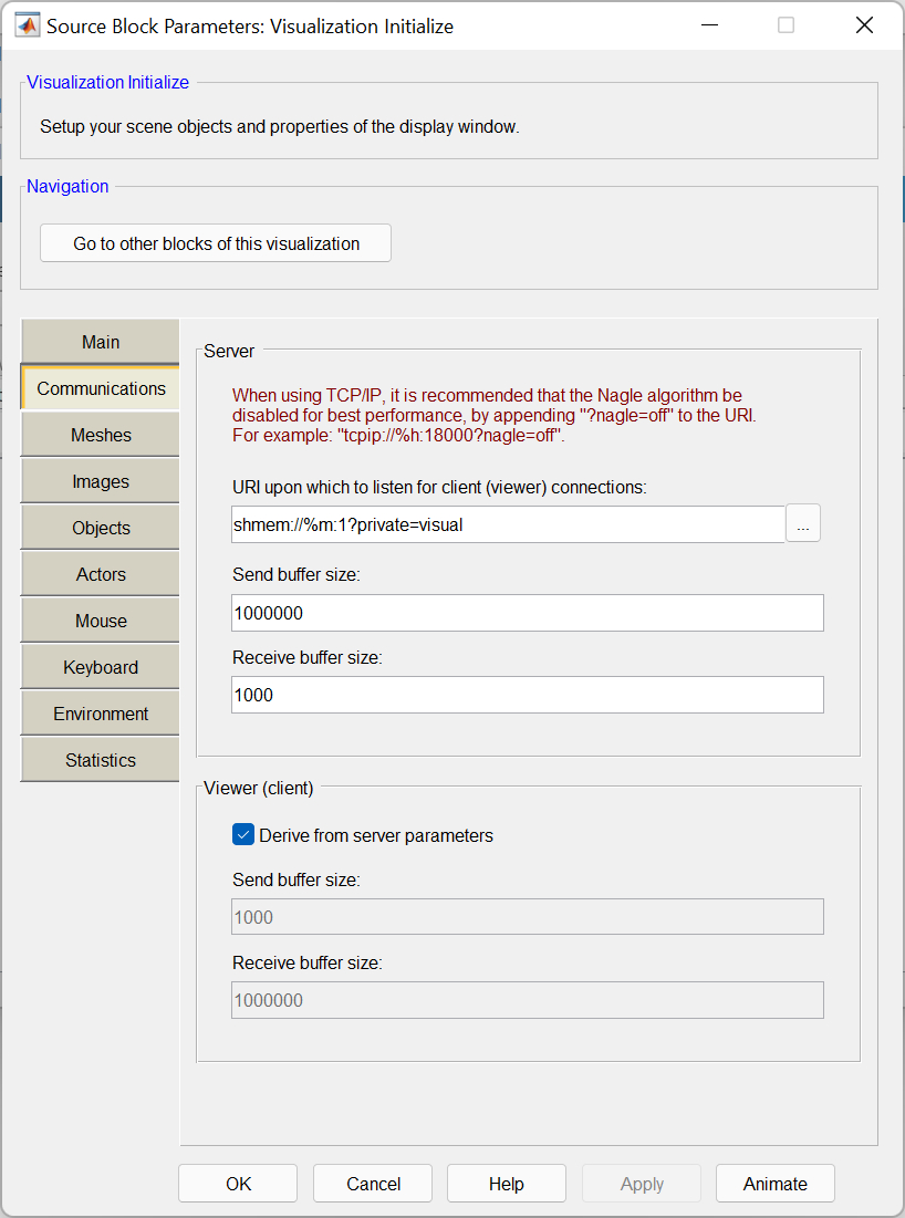
Server URI
This defines the communications method between the server and clients. Supported communication protocols include shared memory, pipes and TCP/IP. Clicking the URI browse button to the right of the field brings up a separate dialog that shows you the available protocols and their associated options.
| If you are using shared memory in Vista with external mode, then it requires that the local option be off (default). Using shared memory in Vista with normal simulation, requires that the local option be on: shmem://%m:2?local="on" |
| If you are using TCP/IP, it is suggested that the Nagle algorithm be disabled. This makes less efficient use of your bandwidth for remote clients, but they receive more frequent animation updates resulting in smoother animation. This can be done by appending the TCP/IP URI with the nagle option: tcpip://localhost:17001?nagle="off" |
| If you are using multiple visualization blocks in your diagram, be sure to use a separate port number for each server URI. |
Server send buffer size (tunable offline)
The send buffer size of the server in bytes. At a minimum, it must be 8 bytes + 4*(number of transmitted elements) such that it can hold a single frame of data.
Server receive buffer size (tunable offline)
The receive buffer size of the server in bytes. At a minimum, it must be 14 bytes. This buffer size is multiplied by the number of clients that connect (a dedicated receive buffer is created for each connected client).
Derive from server parameters (tunable offline)
Checking this box will disable the client send buffer size and receive buffer size fields. It will also set the client send buffer size equal to the server receive buffer size, and the client receive buffer size equal to the server send buffer size.
Client send buffer size (tunable offline)
The send buffer size of the client in bytes. At a minimum, it must be 14 bytes.
Client receive buffer size (tunable offline)
The receive buffer size of the client in bytes. At a minimum, it must be 8 bytes + 4*(number of transmitted elements) such that it can hold a single frame of data.
Meshes Pane
The Meshes pane of the dialog appears as follows:
Mesh Pool (tunable offline)
All of the 3D geometry in the visualization must first be loaded into the mesh pool. The 3D geometry must be in the x3d or proprietary q3d format. The visualization includes plugins for the open-source modelling software Blender, and Autodesk's 3ds Max. See the respective Blender and 3ds Max plugin pages for more details. A number of meshes are also included in the $(QUARC_DIR)/resources/meshes MATLAB Command Line Click to copy the following command line to the clipboard. Then paste it in the MATLAB Command Window: dos(sprintf('explorer.exe "%s" &', fullfile(qc_root, 'resources', 'meshes'))); folder. You can create q3d files by converting an x3d file using the qc_convert_to_q3d function. Since the q3d file format is binary, it can be significantly smaller than the x3d ASCII files.
Clicking the button brings up the dialog shown below.
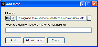
You can either manually enter the path to the x3d file, or you can click the browse button to the right of the field. Clicking the "C:\" or "..\" buttons switch between relative and absolute paths (if a relative path cannot be determined it will default to an absolute path). If you are storing your associated meshes in the same folder or a subdirectory, then using a relative path makes your files more portable if you want to move the location of your folder. Note that a relative path is relative to the location of the scene file, not your model.
After you have selected your file, you can either manually enter a resource identifier that will be used to identify the mesh from the Add object dialog, or you can leave it blank in which case the name "mesh.filename" will be assigned.
There are now two options. If you click the button, then the mesh will be added and you will need to create an object that references the mesh, and an actor that references the object. If you click the button, then an object and actor will be automatically created for you. Note that the button is only available when you are adding a new mesh. The option is not available when editing an existing mesh in the pool.
After adding a mesh to the pool, you can click the button to modify the filename or reference identifier, you can click the button to remove a mesh (actor and object dependencies must be removed first), and you can click the button to preview the mesh. The mesh preview is limited to rotating the mesh by click-dragging the mouse on the viewer. For more advanced preview capabilities, see the Visualization Animate Dialog page.
Images Pane
The Images pane of the dialog appears as follows:
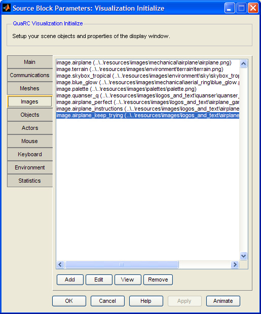
Image Pool (tunable offline)
While models give us the basic shapes of our world, we can really make the worlds come to life when we can paint details on top of the 3D geometry. This is called texture mapping.
If you want to texture map your meshes, then there are three requirements. First, the mesh must have a TextureCoordinate entry in the x3d file to provide mapping coordinates. This tells the rendering engine where each piece of the texture map will be placed on the geometry. Second, the image for the texture must have dimensions that are of a power of two (2, 4, 8, 16 ... 2048, 4096, etc) although the image does not need to be square (eg 1024x2048 is acceptable). And third, the texture map must be loaded into the image pool and associated with the object.
Supported file formats include jpg, png, tif, and bmp. The png and bmp file formats support an alpha component for transparency. This can be used to create bunches of leaves on a tree rather than modeling each leave individually in geometry which could be cost prohibitive in terms of your frame rate. You also could use this same technique to create a wire fence on top of one large rectangle. Making use of bitmap opacity can create the appearance of the model having more detail than actually exists in the geometry.
Bitmaps can be created with any paint program that supports these formats. You can use packages such as the open-source image editor GIMP, commercial packages such as Adobe's Photoshop, or even Microsoft Paint in Windows. A number of images which are designed to work with the included x3d files are also included in the $(QUARC_DIR)/resources/images MATLAB Command Line Click to copy the following command line to the clipboard. Then paste it in the MATLAB Command Window: dos(sprintf('explorer.exe "%s" &', fullfile(qc_root, 'resources', 'images'))); folder.
Clicking the button brings up the dialog shown below.
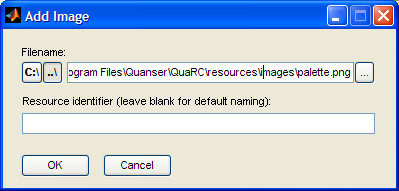
You can either manually enter the path to the image file, or you can click the "..." browse button to the right of the field. Clicking the "C:\" or "..\" buttons switch between relative and absolute paths (if a relative path cannot be determined it will default to an absolute path).
| If you store your associated images in the same folder or a subdirectory, then using a relative path makes your files more portable. Note that a relative path is relative to the location of the scene file, not your model. |
After you have selected your file, you can either manually enter a resource identifier that will be used to identify the image from the Add object dialog, or you can leave it blank in which case the name "image.filename" will be assigned. Click to add the image to the image pool.
After adding an image to the pool, you can click the button to modify the filename or reference identifier, you can click the button to remove an image (actor and object dependencies must be removed first), and you can click the button to view the image.
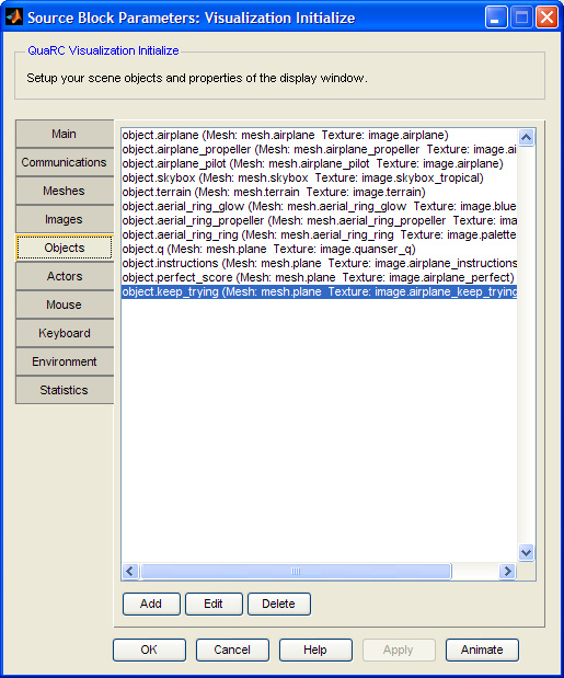
Objects Pane
The Objects pane of the dialog appears as follows:

Object Pool (tunable offline)
Objects are used to attach textures to meshes. By combining a single mesh with several different texture maps, you can create objects with a unique appearance while conserving on memory.
Clicking the button brings up the dialog shown below.
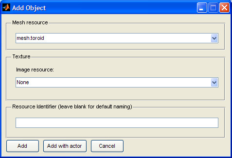
From the Mesh resource popup menu, you can select the associated mesh. Every object must reference a single mesh. From the Image resource popup menu, you can select an associated texture map. If the image resource is set to None, then the mesh will be a solid color dictated by the actor parameters.
After you have selected your resources, you can either manually enter a resource identifier that will be used to identify the object from the Add actor dialog, or you can leave it blank in which case the name "object.mesh_name" will be assigned.
There are now two options. If you click the button, then the object will be added and you will need to create an actor that references the object. If you click the button, then an actor will be automatically created for you. Note that the button is only available when you are adding a new object. The option is not available when editing an existing object in the pool.
After adding an object to the pool, you can click the button to modify the associated resources, or you can click the button to remove an object (actor dependencies must be removed first).
Actors Pane
The Actors pane of the dialog appears as follows:
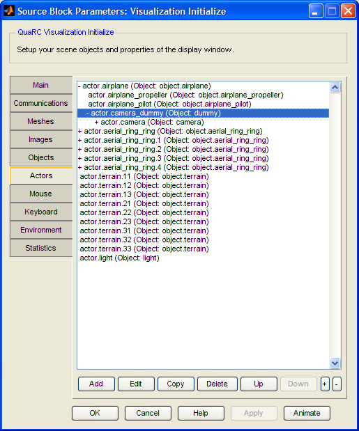
Actor Pool (tunable offline)
Actors are what actually show up in the visualization. Clicking the button brings up the dialog shown below.
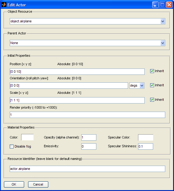
Object Resource
From the popup menu, you can select from the following options:
|
Object |
Description |
|---|---|
|
User defined object |
Any of the objects created in the object pool will be listed here by their associated resource identifier. Multiple actors can reference a single object. |
|
Light |
Although a light is not required, most scenes will contain at least one light. OpenGL has a restriction of a maximum of 8 lights in a scene, however, each light adds to the computational load, so it is generally best to minimize the number of lights if possible. All lights are omni-directional point light sources and therefore not affected by orientation or scale, however, these properties will be passed on to any child objects. |
|
Dummy |
Dummy objects are not normally visible in the scene (they can be made visible in the viewer with the Show Dummy Actors option), but they can be helpful to serve as intermediate objects if you want to shift the origin or point of rotation of an existing object. They can also be used to create certain special effects such as planar shadows (see the Visualization Shadows page for more details). Dummy objects are not affected by color or opacity. |
|
Camera |
Every scene will contain a single camera that is added by default to the actor list. The camera is not affected by scale, color, or opacity. The camera can be a child actor of other actors, and other actors can be a child of the camera. This makes it possible to attach a camera to a vehicle, and then attach user interface elements such as a speedometer to the camera so that it will always be visible to the user regardless of where the camera is pointed. |
Parent Actor
If you want to drive the parameters of the actor independently of all the other actors in the world, then the Parent Actor should be set to None. However, if you want to create something like a robot arm, then the base component will have no parent, but each subsequent linkage will specify the previous linkage as its parent. Therefore, by default, the child actor will inherit all the position, orientation, and scale factors applied to the parent. Transformations applied to the child will be made with respect to the parent. If you only want some of the properties to be inherited (such as the position, but not the orientation to create joint angles with respect to the world space), then modify the associated inheritance properties in the Initial Properties section.
Initial Position
Sets the initial position of the actor with respect to the parent. If no parent is specified, then this is an absolute position. The "Absolute" text information tells you what the absolute position is based on the parent's current initial properties. Unchecking the associated Inherit checkbox will drive this actor's position independently of the parent. The position is in units.
Initial Orientation
Sets the initial orientation of the actor with respect to the parent. If no parent is specified, then this is an absolute orientation. The "Absolute" text information tells you what the absolute orientation is based on the parent's current initial properties. Unchecking the associated Inherit checkbox will drive this actor's orientation independently of the parent. The current units of the orientation can be changed between radians and degrees using the drop-down box to the right. The units will be saved in radians in the scene file.
Initial Scale
Sets the initial scale of the actor with respect to the parent. If no parent is specified, then this is an absolute scale. The "Absolute" text information tells you what the absolute scale is based on the parent's current initial properties. Unchecking the associated Inherit checkbox will drive this actor's scale independently of the parent, otherwise it will be multiplied. The scale multiplies the vertex position with respect to the objects origin. Note, scale values between 0 and 0.001 will be saturated to 0.001, and values less than 0, but greater than -0.001 will be saturated to -0.001.
Render Priority
This is primarily used to sort transparency conflicts and achieve certain special effects, but it can also be used to improve render efficiently. During a render pass, the actor list is first sorted by render priority, then within each render priority, actors are sorted with opaque objects from front to back, followed by transparent objects from back to front.
If you try to draw a transparent box within another transparent box, then depending on your view position, the inner box may become occluded due to the sorting algorithm rendering the outer box first. This can be corrected by increasing the render priority of the inner box above the outer box such that it will always be rendered first.
You can purposely use the inverse of this effect to allow you to look through an object. If you had an "x-ray machine mesh" in front of another object where the viewer of the x-ray was semi-transparent texture. By setting the render priority of the object you want to see through to be less than the viewer, the viewer would occlude rendering of the object to be seen through, thus allowing you to see the "inner workings" mesh in behind. See the Visualization X-Ray Demo for an example of this effect.
In a case of render efficiency, any object that is texture mapped with a png or bmp image is flagged as a transparent object even when the opacity is set to one. If you know that the rendering of the mesh is not dependent on any alpha components in the associated texture map, then by increasing the render priority above other transparent objects, it will be rendered first, thus treating it as an opaque object. By doing this, the render process will not attempt to render any pixels that are behind the mesh therefore potentially saving some time during the render loop. Note that this is an advanced optimization that is only required if you find that you are not achieving your desired frame rate.
Color
The diffuse color of the actor (see the Visualization Material Properties Demo for the differences between diffuse, specular and emissivity). Clicking on the colored rectangle will bring up a palette dialog from which you can select from a standard color or specify a color in red, green, blue components. The resulting color of the actor will be the color of the texture map multiplied by the diffuse material color multiplied by light color. If an object does not have a texture map, then actor color will only be the material diffuse color multiplied by the light color. If a mesh does not have normal vectors defined, then the mesh will be fully lit and will appear as the selected diffuse color.
Disable fog
The fog parameters (set in the Environment tab) globally affects all actors. If you do not want the fog to affect a particular actor (such as for skyboxes), then this box should be checked.
Opacity
This sets the transparency of the actor. Setting this to a value less than one, but greater than zero will flag the object as transparent and it will be subject to the render sort order as a semi-transparent object. Setting this value to zero will disable rendering of the object. For scene with a large number of actors, you can potentially improve rendering efficiency by setting the opacity of unseen actors to zero rather than just moving them out of view.
Emissivity
Emissivity, also known as self-illumination is like setting the ambient light on a per-ambient basis. An emissivity of 0 disables self-illumination and the mesh will be subject to all diffuse and specular lighting. For an emissivity of 1, the object will be fully illuminated and there will be no shading on the object. The object will take on the diffuse color multiplied by any texture colors. A fully lit object is not subject to any lights in the scene. This can be useful for texture baking, user-interface elements that you do not want to be affected by scene lights, or to create cell-shaded cartoon-like effects. See the Visualization Material Properties Demo for the differences between diffuse, specular and emissivity.
Specular Color
Specular spots are the bright patches that you see on most objects. Unlike diffuse color which is only dependent on the position of the light sources, the specular highlights are a function of the position and distance of the light sources and the position and distance of the camera. See the Visualization Material Properties Demo for the differences between diffuse, specular and emissivity. The color of the highlight is a function of the specular color multiplied with the color of the light source. Plastics typically use a white specular component while metals tend to have a specular color that is similar to the diffuse color. Setting the specular color to black ([0 0 0]) will disable the specular component. Note that specularity is highly dependent on the resolution of your mesh since the lighting is calculated on a per-vertex basis. A low resolution mesh may not show much specular effect. If you view the Visualization Material Properties Demo in the wireframe mode, you can gain an understanding of the level of detail required for different shininess levels.
Specular Shininess
The shininess works in conjunction with the specular color. A positive value close to zero will create a large bright spot. A value close to 1 will make a very small bright spot.
After you have configured your actor, you can either manually enter a resource identifier that will be used to identify the actor as a parent actor from the Add actor dialog, or you can leave it blank in which case the name "actor.object_name" will be assigned. Clicking will add the actor to the pool.
After adding an object to the pool, you can click the button to modify the actor parameters, or you can click the button to remove an actor. The button will duplicate the existing selected actor. The and buttons can be used to rearrange the order of the actors between siblings. As you create a hierarchical structure with parent-child relationships, the actor list will arrange itself into a tree structure. Clicking on an actor with a "+" next to it while holding down the Alt key will expand the tree. The "+" and "-" buttons at the bottom will expand or collapse the entire tree. Double-clicking on an actor will allow the actor to be edited.
Mouse Pane
The Mouse pane of the dialog appears as follows:
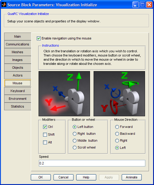
Enable navigation (tunable offline)
This enables the configured mouse controls. If mouse controls are not enabled, but the menu is shown in the viewer, the mouse controls can be enabled in the viewer with the default mouse controls. Note that unlike the Host Mouse block, these controls are only active when the viewer window is active.
Modifiers, Buttons, Mouse Direction, and Speed (tunable offline)
There are six axes that can be configured for the mouse. By clicking on each of the six axes shown in the two images with the cameras, the controls and speed below are updated to reflect each configuration. For each direction, a modifier can optionally be used in combination with a selected mouse button and mouse direction. The arrows point in the positive directions. Selecting the mouse motion forward for the y rotation will cause the camera to rotate down for forward mouse motion. If you prefer the inverse motion, then select the mouse motion backward for the y rotation. A forward mouse motion will now rotate the camera up instead. The speed of each axis can be set independently. This speed constant does not have any meaningful units as it is a function of the resolution of your monitor and your default Windows mouse speed.
Keyboard Pane
The Keyboard pane of the dialog appears as follows:
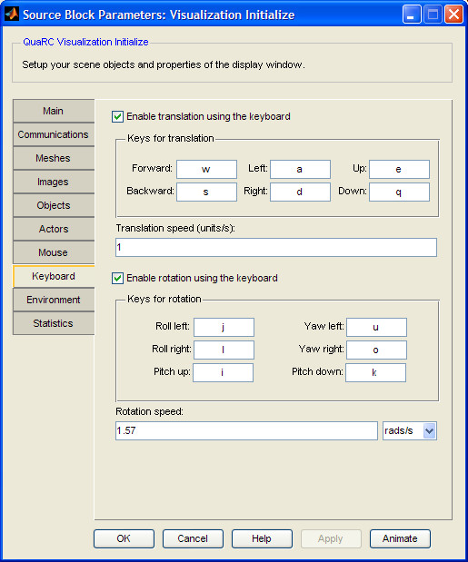
Enable translation using the keyboard (tunable offline)
This enables the configured keyboard translation controls. If the keyboard translation controls are not enabled, but the menu is shown in the viewer, the keyboard translation controls can be enabled in the viewer with the default controls. Note that unlike the Host Keyboard block, these controls are only active when the viewer window is active.
Keys for translation (tunable offline)
There are three axes (six directions) that can be configured for translation. By clicking the mouse in one of the fields then pressing the desired key, the default key will be changed.
| Not all versions of Matlab support all the special function keys. For instance, R2008a and prior does not support the Windows key (it will return "0" instead of "windows"), however, R2008b and above does support the Windows key. |
Translation speed (tunable offline)
When a translation key is held down in the viewer window, the translation speed is the rate at which the camera will be manually manipulated in units per second.
Enable rotation using the keyboard (tunable offline)
This enables the configured keyboard rotation controls. If the keyboard rotation controls are not enabled, but the menu is shown in the viewer, the keyboard rotation controls can be enabled in the viewer with the default controls. Note that unlike the Host Keyboard block, these controls are only active when the viewer window is active.
Keys for rotation (tunable offline)
There are three axes (six directions) that can be configured for translation. By clicking the mouse in one of the fields then pressing the desired key, the default key will be changed.
| Not all versions of Matlab support all the special function keys. For instance, R2008a and prior does not support the Windows key (it will return "0" instead of "windows"), however, R2008b and above does support the Windows key. |
Rotation speed (tunable offline)
When a rotation key is held down in the viewer window, the rotation speed is the rate at which the camera will be manually manipulated. The displayed units of the rate of rotation can be selected by the drop-down box to the right. The value will be stored in radians in the scene file.
Environment Pane
The Environment pane of the dialog appears as follows:
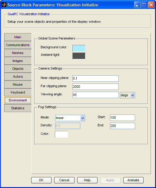
Background color (tunable offline)
The background color is the color on which all objects will be drawn. It is not affected by lighting. If a sky box is being used, this color typically will not be seen.
Ambient light (tunable offline)
Ambient light is the color that will be used for the sections of objects that are not directly lit by a light actor. The lighting is determined by the dot product of the normal vector with the light vector. A dot product less than, or equal to zero will be shaded the ambient color.
Near clipping plane (tunable offline)
Rendering efficiency is improved by use of a depth buffer which keeps track of how far into the view pixels reside. This prevents pixels that are behind an existing object from being rendered unnecessarily. The range of the depth buffer you set by the near and far clipping planes. Any pixel that would be drawn closer to the camera than the near clipping plane will not be drawn.
| If there appears to be "Z fighting" in your scene (an object that should be behind another is partially visible, often with a flickering appearance), then try setting your near clipping plane further from the camera to increase the resolution of your depth buffer. |
Far clipping plane (tunable offline)
Rendering efficiency is improved by use of a depth buffer which keeps track of how far into the view pixels reside. This prevents pixels that are behind an existing object from being rendered unnecessarily. The range of the depth buffer you set by the near and far clipping planes. Any pixel that would be drawn further from the camera than the far clipping plane will not be drawn.
| Note, if there appears to be "Z fighting" in your scene (an object that should be behind another is partially visible, often with a flickering appearance), then try setting your far clipping plane closer to the camera to increase the resolution of your depth buffer. |
View angle (tunable offline)
The view angle defines the width of your field of view. A typical value is around 45 degrees. A view angle of 10 degrees is like a telephoto lens which will effectively zoom your view in towards your objects. A view angle of 90 degrees is like a wide angle lens and you will see significant distortion towards the corners of your view. The displayed units of the rate of rotation can be selected by the drop-down box to the right. The value will be stored in degrees in the scene file.
Fog Settings (tunable offline)
There are three types of fog available:
|
Mode |
Equation |
Notes |
|---|---|---|
|
none |
This disables all fog. |
|
|
linear |
|
Given a z distance from the camera, the fog is calculated based on the start and end parameters. Density is not used. |
|
exp |
|
Given a z distance from the camera, the fog is calculated based on the density parameter. The density parameter must be a positive value greater than zero. The start and end parameters are not used. |
|
exp2 |
|
Given a z distance from the camera, the fog is calculated based on the density parameter. The density parameter must be a positive value greater than zero. The start and end parameters are not used. |
| To effectively make use of fog, it is suggested that you select a fog color that matches the background color of your scene. This can be further enhanced by fading the actor's alpha component with a Set Variables block as it moves into the fog. By eventually setting the alpha value to zero, you will disable rendering of that actor. A more advanced version of this concept could include fading out mountains in the distance, but at the same time fading in a lower-resolution mesh so you can maintain the fogged silhouette of the mountains, while reducing the computational load on the graphics card. |
| By default, all objects are affected by the fog. If you want specific objects to not be affected by fog (such as a sky box for instance), check the Disable fog parameter in the Edit Actors dialog. |
Statistics Pane
The Statistics pane of the dialog appears as follows:
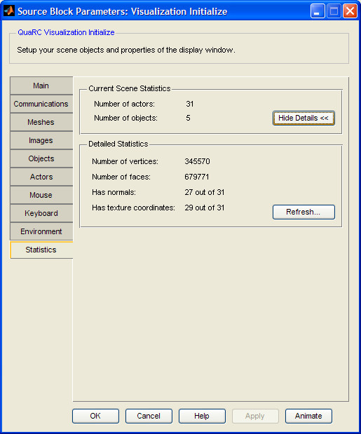
Show Details and Refresh (tunable offline)
The statistics tab gives you some basic information about the scene so you can estimate the computational load. The initial information you are presented with is the total number of actors and objects. Clicking the button will scan all of the mesh files referred to by the objects and return the total number of vertices and faces for all the actors in your scene. It will also indicate how many of the actors have normals and texture coordinates (the camera and lights never have texture coordinates or normals).
The detailed information is not updated when you make changes to your scene file or meshes. After the details are already shown, you can click the button to update the statistics. This will rescan all of the relevant mesh files again to determine if there have been any changes.
Targets
|
Target Name |
Compatible* |
Model Referencing |
Comments |
|---|---|---|---|
|
Yes |
Yes |
||
|
Yes |
Yes |
||
|
Yes |
Yes |
||
|
Yes |
Yes |
||
|
Yes |
Yes |
||
|
Yes |
Yes |
||
|
Yes |
Yes |
||
|
Yes |
Yes |
||
|
Yes |
Yes |
||
|
Yes |
Yes |
||
|
Yes |
Yes |
||
|
Yes |
Yes |
||
|
Yes |
Yes |
||
|
Yes |
Yes |
Last fully supported in QUARC 2018. |
|
|
Rapid Simulation (RSIM) Target |
Yes |
Yes |
|
|
S-Function Target |
No |
N/A |
Old technology. Use model referencing instead. |
|
Normal simulation |
Yes |
Yes |
See Also
Copyright ©2026 Quanser Inc. This page was generated 2026-05-13. Submit feedback to Quanser about this page.
Link to this page.