Quanser QCar 2
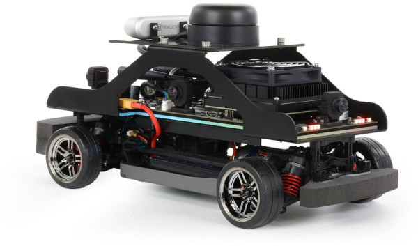
The Quanser QCar 2 is a scale-model car built and sold by Quanser Inc. The QUARC Target associated with the Quanser QCar 2 is the QUARC Linux QCar 2 Target. The QCar 2 driver provides access to the hardware I/O available on the QCar 2 platform. The QCar 2 includes an NVIDIA Jetson AGX Orin board with an ARM Cortex-A78AE processor (2.2 GHz, eight core, 64 bit) as well as an NVidia GPU (930 MHz, 1792 CPU cores, 56 Tensor cores, Ampere architecture) with CUDA support, 360 degree camera view via four wide-angle 8MP cameras, an Intel D435 RGBD camera and additional I/O supplied by Quanser. There is also a Pi connector for an additional IMX219, IMX477 or OV9281 camera. The additional I/O includes:
The QUARC driver name for this card is qcar2. The latest operating system installed on the Quanser QCar 2 is a customized version of Linux for Tegra from JetPack 5.1.4.
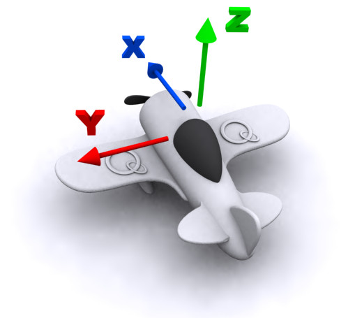
The Quanser QCar 2 uses the Quanser standard reference frame for unmanned vehicles, as shown below:
To select the Quanser QCar 2 board, select the QUARC qcar2 board type from the drop-down list on the Main tab of the HIL Initialize block. Please note that only one QCar 2 card can be connected to a Quanser QCar 2 and is supported in the system. The QUARC controller runs on the NVIDIA Jetson AGX Orin board.
| Note that the Linux QCar 2 target must be selected to use the QCar 2 board, as it is connected to the NVIDIA Jetson AGX Orin board. |
The Quanser QCar 2 supports three different means of communicating with it as a target. It supports wireless (WiFi) communications, which are most readily configured initially by connecting a monitor, mouse and keyboard and using the Ubuntu desktop to connect to the WiFi router. If a wireless connection is used then its IP address will show up on the LCD display with a WiFi symbol beside it. Once configured, it should reconnect automatically whenever the WiFi signal is available.
The Quanser QCar 2 also supports a 10/100/1000 Mbps wired LAN connection. If the LAN connection is used, its IP address will show up on the LCD display with a LAN symbol beside it. In the case of WiFi or LAN the IP address is determined by the adapter settings. Typically, the IP address is assigned dynamically by a DHCP server on the network.
Finally, the USB-C On-the-Go port acts as an Ethernet connection when it is connected to a PC. In this case, the IP address will not be shown on the LCD display but the address is always the same and will be 192.168.55.1. The PC to which it is connected will also be assigned an IP address on this "network", such as 192.168.55.100.
| The Quanser QCar 2 implements overcurrent protection to prevent damage to the motor. If an overcurrent condition is detected, the motor will be disabled until the user's application is restarted or the car is rebooted. An overcurrent condition is detected if the motor current exceeds 5A for 2 seconds, or 10A for 0.5 seconds, or 15A for 0.125 seconds. |
To use the 33 bottom LEDs, use the LED Strip block instead of the HIL blocks.
Configuration
The Quanser QCar 2 is configured for the 3S battery supplied with the vehicle. The car does not support using a 4S battery. The car will shut down if a 4S battery is used.
Display
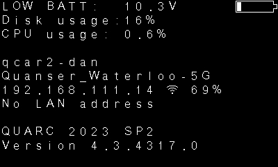
The LCD display normally displays the battery voltage, disk usage, CPU usage, hostname, WiFi SSID, WiFi IP address, LAN IP address and QUARC version on the QCar. It also shows the current WiFi signal strength. The following table shows some of the different status messages that may be displayed by the QUARC Power Monitor daemon on the LCD display. The power monitor only updates the display every ten seconds by default.
|
Display |
Description |
|---|---|
|
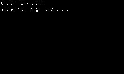
|
Initial message indicating the LCD is powered and working. |
|
|
Shows the hostname for the Quanser QCar 2 and indicates it is booting Ubuntu. |
|
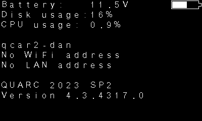
|
Battery voltage. No IP address has been obtained yet. |
|
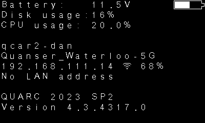
|
Battery voltage and WiFi IP address. No LAN address. |
|
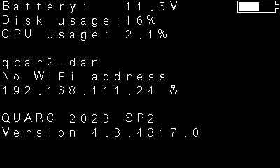
|
Battery voltage and LAN IP address. No WiFi address. |
|
|
Battery voltage and both WiFi and LAN IP addresses. |
|
|
The battery is low. The QCar may soon shut down. Save your work. The default threshold for the low battery warning is 10.5V. |
|
|
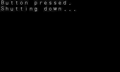
The red power button has been pressed and the Quanser QCar 2 is shutting down. |
|
|
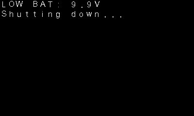
The battery is too low and the Quanser QCar 2 is shutting down. The default threshold for low battery shutdown is 10V. |
|
|
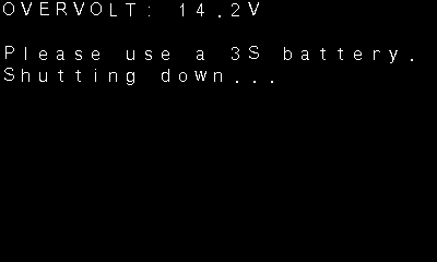
A 4S or higher battery has been used so the voltage is too high and the Quanser QCar 2 is shutting down. The threshold for detecting overvoltage is 13.86V. |
|
|
The red power button has been held for more than four seconds. Releasing it will cause an immediate power-down (not recommended). |
|
|
An overcurrent condition has been detected. It will not be possible to drive the motors until the condition is cleared. To clear the condition, re-run your application. |
|
|
The AGX Orin has not been detected. This warning can indicate a severe problem with the board. Power the board off and ensure the AGX Orin is seated properly and securely mounted with the screws. If it is still not detected the car will need to be returned to Quanser for further inspection. |
The LCD display on Quanser QCar 2 is a graphical black and white LCD display. QUARC supports writing text or graphics to the display using the LCD Display block. To use the LCD Display block, set the LCD to and the URI to spi://localhost:1?word=8,baud=45000000,polarity=on,phase=on,memsize=8192,frame=0. The display supports normal mode or dark mode, as well as an image or text. It can also rotate the display. To format text for the display, use the String Print block, which supports a superset of standard C format strings. The display currently supports the Basic Latin character set as well as the Latin-1 Supplement. For images, the resolution of the display is 400 x 240 pixels. Greyscale images will be thresholded at mid-luminance to produce the black and white output. For optimal display of images, use the Image transform block with the Dither (1-bit) algorithm to convert grayscale images to black and white.
Cameras
The QCar supports four onboard 8MP wide-angle cameras and one Intel RealSense D435 camera. While these are accessed using the Video3D Capture and Video Capture blocks, they are listed here for convenience:
|
Camera |
Block |
Device Identifier |
Description |
|---|---|---|---|
|
D435 |
Video3D Capture |
0 |
The RealSense D435 RGDB camera which faces toward the front of the QCar. This camera supports four video streams: RGB (0), infrared left (1), infrared right (2) and depth (0). |
|
8MP CSI |
Video Capture |
0 |
The CSI camera is an 8MP RGB camera with up to 3280x2464 resolution and 160 degree horizontal field of view. It faces the right side of the QCar. It supports frame rates up to 120 Hz (resolution-dependent). |
|
8MP CSI |
Video Capture |
1 |
The CSI camera is an 8MP RGB camera with up to 3280x2464 resolution and 160 degree horizontal field of view. It faces the rear of the QCar. It supports frame rates up to 120 Hz (resolution-dependent). |
|
8MP CSI |
Video Capture |
2 |
The CSI camera is an 8MP RGB camera with up to 3280x2464 resolution and 160 degree horizontal field of view. It faces the left side of the QCar. It supports frame rates up to 120 Hz (resolution-dependent). |
|
8MP CSI |
Video Capture |
3 |
The CSI camera is an 8MP RGB camera with up to 3280x2464 resolution and 160 degree horizontal field of view. It faces the front of the QCar. It supports frame rates up to 120 Hz (resolution-dependent). |
The CSI cameras are 8MP cameras with up to 3280x2464 resolution. The frame rates achievable at each resolution are listed for convenience in the table below:
|
Resolution |
Maximum Frame Rate (FPS) |
Horizontal Field of View |
Vertical Field of View |
|---|---|---|---|
|
3280x2464 |
21 |
100% |
100% |
|
1640x1232 |
80 |
100% |
100% |
|
820x616 |
80 |
100% |
100% |
|
1640x820 |
120 |
100% |
67% |
|
820x410 |
120 |
100% |
67% |
Other resolutions are achievable but will be scaled versions of the resolutions in the above table. Hence, resolutions with a different aspect ratio may appear distorted. Camera resolutions were designed to always provide the full horizontal field of view of the camera rather than provide common video resolutions.
The Intel RealSense D435 camera is a 2MP camera with up to 1920x1080 resolution for the RGB camera and up to 1280x720 resolution on the depth and infrared cameras. The frame rates achievable at each resolution are listed for convenience in the table below. The maximum frame rate of the RGB camera is 60 FPS and of the depth and infrared cameras is 100 FPS, if the appropriate resolution is selected.
| Note that the achievable frame rate is affected by the exposure setting, so poor lighting will likely result in lower frame rates than those listed in the table below. |
The maximum frame rates at each resolution are:
|
Camera |
Resolution |
Maximum Frame Rate (FPS) |
|---|---|---|
|
Depth |
1280x720 |
30 |
|
848x480 |
90 |
|
|
848x100 |
100 |
|
|
640x480 |
90 |
|
|
640x360 |
90 |
|
|
480x270 |
90 |
|
|
424x240 |
90 |
|
|
256x144 |
90 |
|
|
Infrared |
1280x800 |
30 |
|
1280x720 |
30 |
|
|
848x480 |
90 |
|
|
848x100 |
100 |
|
|
640x480 |
90 |
|
|
640x360 |
90 |
|
|
480x270 |
90 |
|
|
424x240 |
90 |
|
|
256x144 |
90 |
|
|
RGB |
1920x1080 |
30 |
|
1280x720 |
30 |
|
|
960x540 |
60 |
|
|
848x480 |
60 |
|
|
640x480 |
60 |
|
|
640x360 |
60 |
|
|
424x240 |
60 |
|
|
320x240 |
60 |
|
|
320x180 |
60 |
The Intel RealSense Viewer application is provided on the Quanser QCar 2 for testing the RGBD camera. It may also be used for calibration and firmware updates
of the RealSense camera. To run the Intel RealSense Viewer, run the realsense-viewer from a Terminal on the QCar. Turn on the Stereo Module
and RGB Camera to see the depth and RGB output from the camera. To update the firmware or calibrate the camera, see the options under the
hamburger menu. Note that the images can be viewed in 2D or 3D mode using the "2D | 3D" options in the top, right. Options for the Stereo Module and RGB Camera
may be adjusted by expanding the respective item.
The Quanser QCar 2 also supports three different cameras on its Pi connector: the IMX219 (Pi RGB camera), the IMX477 (high-quality Pi RGB camera) and the OV9281
(greyscale global-shutter). To select the camera to use, the jetson-io tool is provided. Run the jetson-io tool by opening a terminal
on the Quanser QCar 2 and running the following command:
sudo /opt/nvidia/jetson-io/jetson-io.py
The following page will be presented:
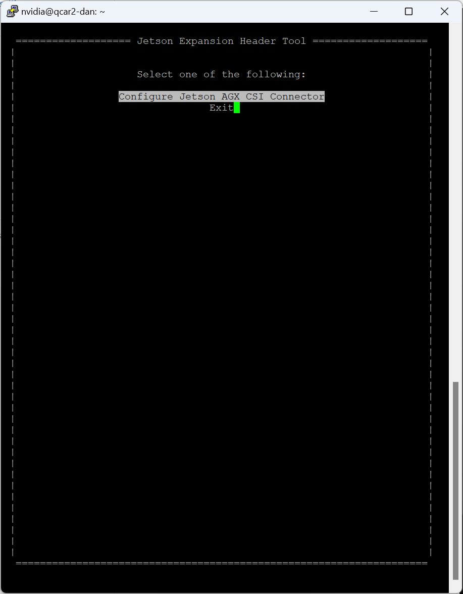
Select the option using the cursor keys and then press Enter to open the connector page, shown below.
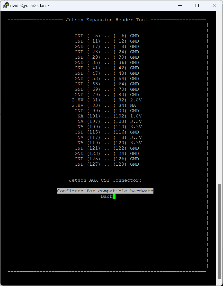
Then select the option using the cursor keys and press Enter to open the compatible hardware page, illustrated below.
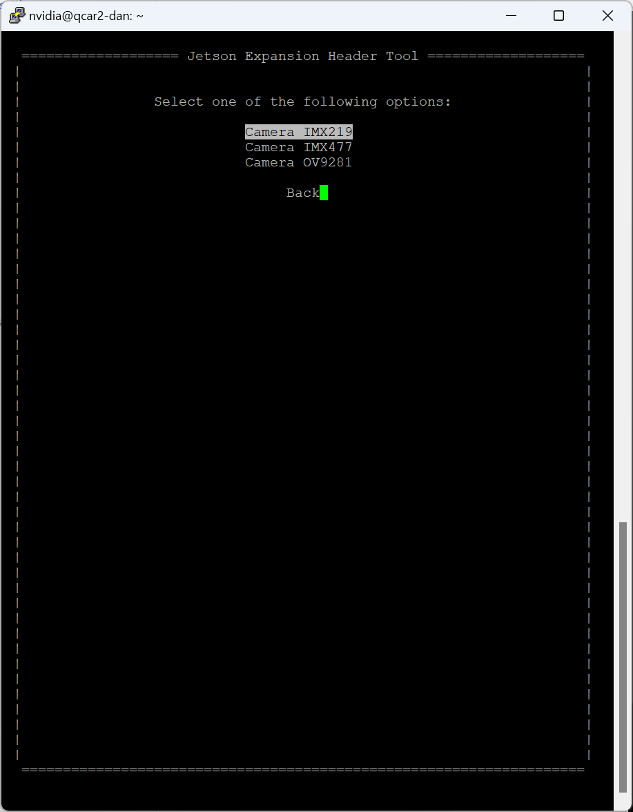
Choose the relevant camera with the cursor keys and press Enter. The camera will be selected and the menu will return to the compatible hardware page. However, this time there will be options to discard the changes or save the changes:
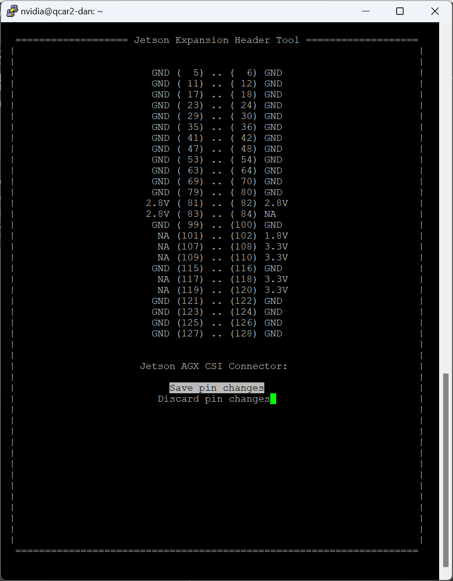
Save the changes by selecting using the cursor keys and pressing Enter. To discard the changes, select instead. When saving the changes, the following page will appear:
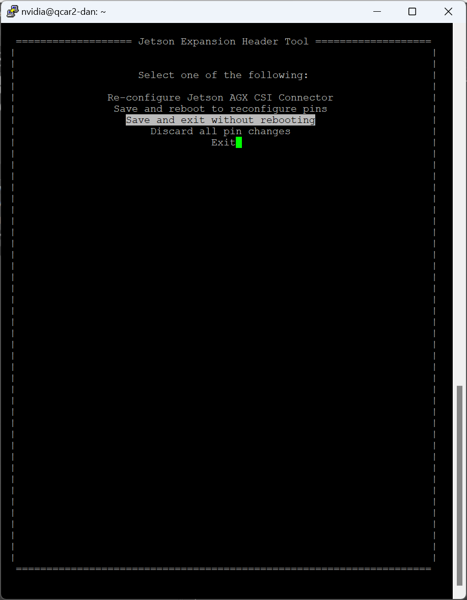
Choose the option using the cursor keys and then press Enter to complete the operation. The final exit page will be shown:
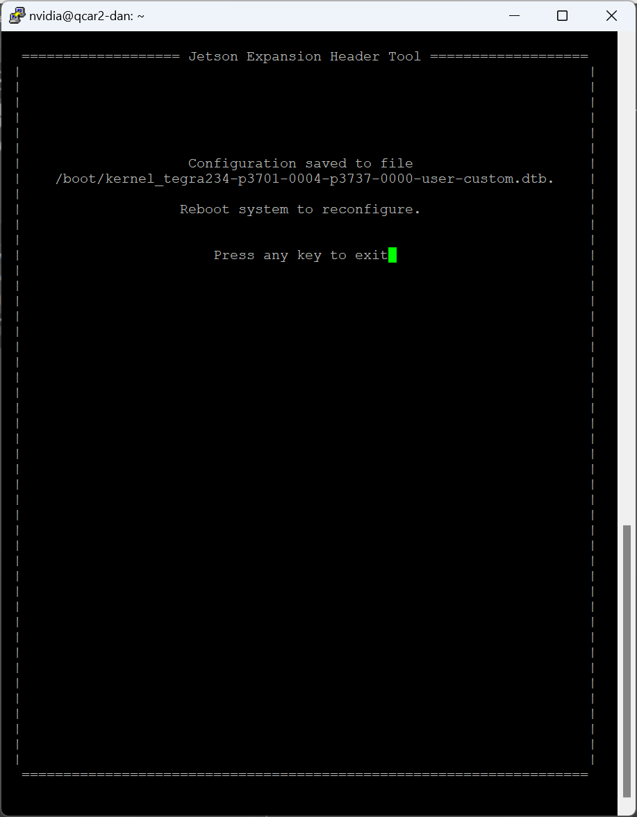
Press Enter to exit the Jetson I/O application. Then shut down the Quanser QCar 2 using the user interface or by issuing a shutdown command:
sudo shutdown now
Connect the selected camera to the Pi connector and power-up the car. The camera should now be available for use.
Communications
The communications ports provided on the QCar board can be utilized through the QUARC Communications blockset and the Quanser Stream API (see QUARC Communications Protocols).
SPI
For SPI communications, a sample URI for communications would be:
spi://localhost:0?baud='1000000',polarity='off',phase='off',lsb='off',frame='0'
where the frame option selects the SPI SS line to frame the SPI bus transaction (0 or 1).
I2C
For I2C communications, a sample URI for communications would be:
i2c://localhost:1?baud='400000',address=0x69
where the address option specifies the I2C slave address. Valid ports are 1 or 7 for I2C1 and IC27 respectively. Note that I2C1 is 3.3V while I2C7 is 1.8V.
| The 1.8V lines are not 3.3V tolerant so be careful not to apply more than 1.8V I2C7! |
Serial
For serial communications, a sample URI for communications would be:
serial://localhost:0?baud='115200',word='8',parity='none',stop='1'
where the port determines whether UART 0 (port 0), UART 1 (port 1) or UART 2 (port 2) is being used. UART 0 is recommended for generic serial devices. It supports baud rates up to 12.5 MBaud. UART2 is more CPU intensive. UART1 is used for the LIDAR, but if the LIDAR is unplugged then its UART may be used as a general-purpose serial port (for GPS or sonar, for example).
The Ranging Sensor block is typically used to talk to the LIDAR rather than using the serial port directly.
CAN Bus
| The CAN bus signals provided on the QCar are not designed to connect directly to a differential CAN bus. To connect to a CAN bus, a transceiver such as the SN65HVD230DR must be used. |
For CAN bus communications, a sample URI for communications would be:
can://localhost:0?flexible='1'
where the port determines whether CAN 0 (port 0) or CAN 1 (port 1) is being used. However, before using CAN bus, the CAN bus network interfaces must be configured. To configure CAN bus, first load the necessary kernel drivers using the commands:
sudo modprobe can
sudo modprobe can_raw
sudo modprobe mttcan
Then to bring up CAN 0 for CAN FD with a 500 kHz standard rate and 2 MHz data rate, use the commands:
sudo ip link set can0 type can bitrate 500000 sjw 4 dbitrate 2000000 dsjw 4 fd on berr-reporting on restart-ms 100
sudo ip link set up can0
Likewise for CAN 1:
sudo ip link set can1 type can bitrate 500000 sjw 4 dbitrate 2000000 dsjw 4 fd on berr-reporting on restart-ms 100
sudo ip link set up can1
The CAN interfaces will now be visible when using the ifconfig command, just like other network interfaces.
Summary
The communications channels are summarized in the table below:
|
Protocol |
Port |
Label |
Sample URI |
Comments |
|---|---|---|---|---|
|
can |
0 |
CAN0 |
can://localhost:0?flexible=1 |
Baud rates are determined when CAN bus network interfaces configured |
|
|
1 |
CAN1 |
can://localhost:1?flexible=1 |
Baud rates are determined when CAN bus network interfaces configured |
|
i2c |
1 |
I2C1 |
i2c://localhost:1?baud=400e3,address=0x6B |
Baud rate is fixed at 400 kHz, 3.3V pins. |
|
|
7 |
I2C7 |
i2c://localhost:7?baud=400e3,address=0x6B |
Baud rate is fixed at 400 kHz, 1.8V only! |
|
serial |
0 |
UART0 |
serial://localhost:0?baud=115200,parity=none,stop=1,flow=none |
Includes hardware flow control signals RTS and CTS |
|
|
1 |
UART1 (LIDAR) |
serial://localhost:1?baud=115200,parity=none,stop=1,flow=none |
No hardware flow control signals. Only use if LIDAR not present. |
|
|
2 |
UART2 |
serial://localhost:2?baud=115200,parity=none,stop=1,flow=none |
No hardware flow control signals. |
|
spi |
0 |
SPI0 |
spi://localhost:0?baud=10000000,polarity=off,phase=off,lsb=off,frame=0 |
Supports two chip selects (0 and 1). |
Audio
The Quanser QCar 2 provides one speaker and four microphones. The microphones are located at the four corners of the car and marked with a microphone symbol for easy identification. The microphones are intended for applications such as user interaction or sound localization, such as detecting the direction from which a honk is heard. If the microphone samples are streamed to a stereo headset on the host PC, the stereo effect is readily apparent.
The two rear microphones are configured as left and right channels of a rear stereo microphone. The device identifier for this rear stereo microphone is "plughw:1,0". Note that only one block or model may open the rear stereo microphone at one time.
The two front microphones are configured as left and right channels of a front stereo microphone. The device identifier for this front stereo microphone is "plughw:1,1". Note that only one block or model may open the front stereo microphone at one time.
To read all four microphones as a single quadraphonic microphone, use the device identifier "plughw:1,2". The purpose of this quadraphonic microphone configuration is to open up the potential for 3D sound localization, such as tracking an overhead drone. Note that only one block or model may open the quadraphonic microphone at one time.
The recommended device identifier for the speaker is "demixer". The demixer device is dynamically assigned based on whether an HDMI monitor with audio support is connected to the car. When an HDMI monitor with audio support is connected, the demixer output will go to the monitor. If the monitor has stereo speakers then stereo sound can be produced. If no HDMI monitor is connected, then the demixer device will output to the car speaker. In this case, the two channels will be mixed as the speaker is monophonic. The demixer device has the additional advantage that it allows the output device to be shared by multiple blocks or models.
| To force the output to the car speaker, use the device identifier "plughw:1,0". Note, however, that in this case access to the speaker will be exclusive. Other blocks or models will not be able to share the speaker. Hence, the "demixer" device is recommended. |
The speaker may be used for honking, engine noises or even user interaction.
Clocks
There is currently one hardware clock that may be used as a timebase for tasks. Its mode and initial frequency are not configurable.
Analog Inputs
The QCar driver supports 5 analog inputs. Hence, analog input channel numbers range from 0 to 4. The analog input range is 0 to +3.3V and is not configurable. Exceeding this range may damage the board. Channels 0-1 are user analog inputs available on the J11 connector.
The battery level in Volts is reported at analog input channel 2. This signal should be monitored to ensure the battery does not degrade below safe levels, particularly for LiPo batteries. For the 3S battery, the voltage should not go below the warning threshold. The default warning threshold is 10.5V. Note that the QCar contains emergency shutdown logic that will attempt to shut down the operating system and turn off the car if the battery voltage falls below the critical threshold. The default critical threshold is 10V.
The current in Amperes used by the electronics is reported on analog input channel 3. This signal indicates how much of the battery current is being used to power the electronics.
The current in Amperes used by the motor is reported on analog input channel 4. This signal indicates how much of the battery current is being used to power the motor.
Analog Outputs
The Quanser QCar 2 card does not support analog outputs.
Digital Inputs
The Quanser QCar 2 supports 11 bidirectional digital I/O lines, as well as three user buttons and an overcurrent condition indicator which act as digital inputs. Hence digital input channel numbers range from 0 to 14. Digital lines 0-4 are available on the J10 connector while lines 5-10 are on the J11 connector. A digital I/O line cannot be used as an input and output at the same time.
| All digital channels are 3.3V. |
| Note that channels 0-4 have better performance than channels 5-10. Hence using the lower digital channels is recommended. |
The first 11 digital I/O lines may be individually programmed as inputs or
outputs on the Quanser QCar 2. All of those 11 channels which will be used for digital inputs
should be configured on the HIL Initialize
block's Digital Inputs tab. Set the Digital input channels field to all
the digital I/O channels that will be used as digital inputs on the board for the current diagram. For example, enter
0:3 to designate channels 0 through 3 as digital inputs. Specify
[0, 4, 5] to indicate that channels 0, 4 and 5 are to be configured
as digital inputs.
Digital Outputs
The Quanser QCar 2 supports 11 bidirectional digital I/O lines and sixteen LEDs for lights and turn signals. Hence digital output channel numbers range from 0 to 26. Digital lines 0-4 are available on the J10 connector while lines 5-10 are on the J11 connector. A digital I/O line cannot be used as an input and output at the same time.
To use the 33 bottom LEDs, use the LED Strip block instead of the HIL blocks.
| All the digital channels are 3.3V. |
| Note that channels 0-4 have better performance than channels 5-10. Hence using the lower digital channels is recommended. |
Since the first 11 digital I/O lines may be individually programmed as inputs or outputs
on the Quanser QCar 2, all the channels which will be used for digital outputs should be configured
on the HIL Initialize block's
Digital Outputs tab. Set the Digital output channels
field to all the bidirectional digital I/O channels that will
be used as digital outputs on the board for the current diagram. For example, enter
0:3 to designate channels 0 through 3 as digital outputs. Specify
[0, 4, 5] to indicate that channels 0, 4 and 5 are to be configured
as digital outputs.
To set the digital output values when the model is loaded or unloaded, set the Initial digital outputs and Final digital outputs to the desired values respectively. If the vectors specified in these fields are shorter than the channel vector, the value of the last element in the vector will be used for the rest of the channels. Hence, a scalar value will apply to all channels specified in the Digital output channels field.
Encoder Inputs
The Quanser QCar 2 supports three quadrature encoder inputs with 24-bit count values. Hence encoder channel numbers range from 0 to 2. Channel 0 is the motor encoder on connector J24. Channels 1-2 are user encoder channels available on connector J11.
In order to set the encoder counters to a particular count or to change the default
quadrature when the model is loaded, the encoder inputs must
be configured on the HIL Initialize
block's Encoder Inputs tab. Set the Encoder input channels
field to all the encoder channels that will be
used on the board for the current diagram. For example, enter 0:2 to
indicate channels 0 through 2 are used as encoder inputs. Specify [0, 2]
to indicate that channels 0 and 2 are used as encoder inputs.
The Quanser QCar 2 supports 2x-quadrature and 4X quadrature. Since the Quanser QCar 2 has 24-bit counters, valid initial count values range from -8,388,608 to +8,388,607. If the vectors specified in these fields are shorter than the channel vector, the value of the last element in the vector will be used for the rest of the channels. Hence, a scalar value will apply to all channels specified in the Encoder input channels field.
The Quanser QCar 2 default sign convention in quadrature (4X) mode increments the encoder counter value when the B channel signal leads the A channel signal. Conversely, the encoder counter value is decreased when A leads B. This sign convention can be changed in the Board-Specific Options, with the enc0_dir option, for encoder channel 0, and with the enc1_dir and enc2_dir options for encoder channels 1 through 2, respectively. See the Board-Specific Options section below for more details.
PWM Outputs
The QCar driver supports 2 PWM output channels. Hence, PWM output channels range from 0 to 1. The PWM channels must share the same PWM frequency. However, each channel can have its own duty cycle. PWM channels available on connector J11.
In order to configure the PWM mode or frequency, or to set the value of the PWM outputs when the model is loaded or unloaded, the PWM
outputs must be configured on the HIL Initialize block's
PWM Outputs tab. Set the PWM output channels field to all the PWM output channels that will be used on the
board for the current diagram. For example, enter 0:1 to indicate channels 0 and 1. Specify 1 to indicate channel 1 alone.
The PWM outputs are generic PWM outputs that are capable of producing conventional PWM, as well as the standard analog ESC protocols, namely standard PWM (1000us to 2000us), Oneshot125 (125us to 250us), Oneshot42 (42us to 84us) and Multishot (5us to 25us).
The ESC Output block is recommended for constructing the input to the PWM output channel since it allows a 0% to 100% throttle value to be used, and it will output the appropriate pulse time (for PWM-based protocols). Note that when using the ESC Output block, the PWM mode should be PWM_TIME_MODE (4) for PWM-based protocols.
The PWM parameters for each of these ESC protocols are tabulated below:
|
Protocol |
PWM Frequency |
Pulse Time Range |
Duty Cycle Range |
|---|---|---|---|
|
Standard PWM |
50 Hz (20ms) |
0.001 to 0.002 seconds (1ms to 2ms) |
0.05 to 0.1 (5% to 10%) |
|
Oneshot125 |
2000 Hz (500us) |
125e-6 to 250e-6 seconds (125us to 250us) |
0.25 to 0.5 (25% to 50%) |
|
Oneshot42 |
5952 Hz (168us) |
42e-6 to 84e-6 seconds (42us to 84us) |
0.25 to 0.5 (25% to 50%) |
|
Multishot |
20000 Hz (50us) |
5e-6 to 25e-6 seconds (5us to 25us) |
0.1 to 0.5 (10% to 50%) |
The PWM outputs are not restricted to these parameter values as they are generic PWM outputs. The maximum output frequency is 180 MHz. The number of bits of resolution decreases with increasing PWM output frequency.
Set the PWM output frequency (a.k.a., pulse rate) in the "Frequencies in Hz or duty cycle" field. The
PWM output mode is typically set to duty cycle mode (0) or time mode (4) when driving ESCs or R/C servos.
Set the Initial PWM outputs and Final PWM outputs fields to the desired
initial and final output values respectively. The interpretation of these output values depends on the PWM mode selected.
If the vectors specified in these fields are shorter than the channel vector, the value of the last element in the vector
will be used for the rest of the channels. Hence, a scalar value will apply to all channels specified in the PWM output channels field.
Likewise, for the PWM output mode for example, the default value is [0 0] so that the first '0' applies
to the motor PWM, which must be duty cycle mode (0), and the second '0' applies to the rest of the PWM channels.
Other Inputs
The specific Other Input channels of the Quanser QCar 2 board are described in the table below. SI units are used.
|
Other Input Channel |
Measurement Description |
Units |
|---|---|---|
|
3000, 3001, 3002 |
Angular velocity around the x-, y-, and z-axis, respectively (from gyroscope) |
(rad/s) |
|
4000, 4001, 4002 |
Linear acceleration along the x-, y-, and z-axis, respectively (from accelerometer) |
(m/s2) |
|
10000 |
Temperature of IMU sensor. |
(C) |
|
14000 |
Motor velocity. |
(counts/s) |
|
14001 |
Encoder 1 velocity. |
(counts/s) |
|
14002 |
Encoder 2 velocity. |
(counts/s) |
Channel numbers for Other Input or Output channels use predefined ranges for each type of measurement to ensure consistency between data acquisition devices. Refer to QUARC Other Channels for a list of the Other Input or Output channel number ranges defined for any HIL Data Acquisition Card and their SI units.
Note that the IMU may be read at any time, but measurements are updated internally at a fixed 32 kHz rate. The gyroscope and accelerometer can produce new values at this rate. The output data rate for the different IMU components may be set in the board-specific options (see below).
Other Outputs
The specific Other Output channels of the Quanser QCar 2 board are described in the table below. SI units are used.
|
Other Output Channel |
Measurement Description |
Units |
|---|---|---|
|
1000 |
Steering angle |
(rad) |
|
11000 |
Motor throttle |
(%) |
Channel numbers for Other Input or Output channels use predefined ranges for each type of measurement to ensure consistency between data acquisition devices. Refer to QUARC Other Channels for a list of the Other Input or Output channel number ranges defined for any HIL Data Acquisition Card and their SI units.
The steering angle is tranlated into an RC servo command that is sent to the steering servomotor connected to J25.
Interrupts
The Quanser QCar 2 card, or its driver, does not support any interrupt sources.
Watchdog
The Quanser QCar 2 contains a programmable 16-bit watchdog timer. The timer may be programmed with any interval between 81.88 microseconds and 2.684 seconds. The board will reset digital outputs 5-10, PWM outputs 0 and 1, and other outputs to the user-configured values when the watchdog expires. Resetting of the outputs occurs without software intervention, and therefore may be used as a safety mechanism in the event of software failure. Note that digital outputs 0-4 cannot be reset on watchdog expiration and the steering analog and motor throttle may only be reset to zero.
Place a HIL Watchdog block in the diagram to program the 16-bit watchdog timer. This block also reloads the watchdog each time it is executed.
Once the watchdog has expired, further I/O is disabled until the watchdog state is cleared.
Hence, in Simulink models, the outputs will remain reset after watchdog expiration even after the model is stopped, unless a HIL Watchdog Clear block is used to clear the watchdog state. Restarting the model also causes the watchdog state to be cleared, allowing the outputs to be used once more. These semantics make the watchdog useful for ensuring product safety.
Board-Specific Options
The Quanser QCar 2 has a number of board-specific options to control specialized functionality of the Quanser QCar 2. These options configure the IMU and set the encoder directions.
gyro_fs
This option sets the full-scale range of the gyroscope sensor. Valid values range from 15.625 to 2000. The units are degrees per second.
gyro_rate
This option sets the gyroscope sensor's sampling rate. Valid values range from 12.5 to 32000. The units are Hz.
gyro_ord
This option sets the gyroscope sensor's filter order. Valid values range from 1 to 3.
gyro_bw
This option sets the gyroscope sensor's filter bandwidth. Valid values range from 10 to 16000. The units are Hz.
accel_fs
This option configures the full-scale range of the accelerometer. Valid values are 2 to 16. The units are g's.
accel_rate
This option sets the accelerometer's sampling rate. Valid values range from 12.5 to 32000. The units are Hz.
accel_ord
This option sets the accelerometer sensor's filter order. Valid values range from 1 to 3.
accel_bw
This option sets the accelerometer sensor's filter bandwidth. Valid values range from 10 to 16000. The units are Hz.
enc0_dir
Set this option to "yes", "y" or "1" to reverse the direction of encoder 0. This feature makes it easier to migrate to the Quanser QCar 2 hardware from another data acquisition card. It also allows models to be more portable to other cards.
Similar options exist for the other encoder channels i.e., enc1_dir and enc2_dir.
steer_bias
The QCar 2 chassis sometimes has a bias in the steering so that driving the steering output with zero does not produce a zero angle on the wheels i.e., the car may not drive in a straight line when the steering output is set to zero. To adjust for this bias, the steer_bias option may be used to add a small offset to the steering output to eliminate this bias. The value specified should be in radians and may be positive or negative as appropriate. Suitable values are typically between 0.03 and 0.09.
temp_bw
This option sets the temperature sensor's filter bandwidth. Valid values range from 5 to 4000. The units are Hz.
Properties
The Quanser QCar 2 supports the following integer properties:
|
Property Name |
Property Code |
Description |
|---|---|---|
|
PROPERTY_INTEGER_FIRMWARE_MAJOR_VERSION |
10 |
The major version of the firmware. |
|
PROPERTY_INTEGER_FIRMWARE_MINOR_VERSION |
11 |
The minor version of the firmware. |
|
PROPERTY_INTEGER_FIRMWARE_BUILD |
12 |
The build of the firmware. |
|
PROPERTY_INTEGER_FIRMWARE_REVISION |
13 |
The PCB revision. |
|
PROPERTY_INTEGER_NUMBER_OF_ANALOG_INPUTS |
16 |
The number of analog input channels. |
|
PROPERTY_INTEGER_NUMBER_OF_ENCODER_INPUTS |
17 |
The number of encoder input channels. |
|
PROPERTY_INTEGER_NUMBER_OF_DIGITAL_INPUTS |
18 |
The number of potential digital input channels. |
|
PROPERTY_INTEGER_NUMBER_OF_OTHER_INPUTS |
19 |
The number of other input channels. |
|
PROPERTY_INTEGER_NUMBER_OF_ANALOG_OUTPUTS |
20 |
The number of analog output channels. |
|
PROPERTY_INTEGER_NUMBER_OF_PWM_OUTPUTS |
21 |
The number of PWM output channels. |
|
PROPERTY_INTEGER_NUMBER_OF_DIGITAL_OUTPUTS |
22 |
The number of potential digital output channels. |
|
PROPERTY_INTEGER_NUMBER_OF_OTHER_OUTPUTS |
23 |
The number of other output channels. |
|
PROPERTY_INTEGER_NUMBER_OF_CLOCKS |
24 |
The number of clocks. |
|
PROPERTY_INTEGER_NUMBER_OF_INTERRUPTS |
25 |
The number of interrupt channels. |
Connectors
The Quanser QCar 2 board has a number of connectors for expansion I/O. These connectors and their pinouts are listed below.
| Note that all pins are 3.3V and are not 5V tolerant unless marked otherwise. Be aware that some of the I/O are 1.8V and are not 3.3V tolerant. The analog inputs only support 0 to +3.3V. Exceeding these voltages may damage the board! |
J10 Connector (I2C)
Ground ― | 24 | 23 | ― 3.3V |
UART0 RX → | 22 | 21 | ― 1.8V |
UART0 CTS → | 20 | 19 | → UART0 RTS |
DIO0 ↔ | 18 | 17 | → UART0 TX |
DIO1 ↔ | 16 | 15 | → SPI0 CS0 |
DIO2 ↔ | 14 | 13 | → SPI0 CS1 |
DIO3 ↔ | 12 | 11 | → SPI0 COPI |
DIO4 ↔ | 10 | 9 | ← SPI0 CIPO |
I2C1 SDA ↔ | 8 | 7 | → SPI0 CLK |
I2C1 SCL ↔ | 6 | 5 | ― Ground |
I2C7 SDA ↔ | 4 | 3 | ← DEBUG RX |
I2C7 SCL ↔ | 2 | 1 | → DEBUG TX |
J11 Connector (GPIO, ENCs, PWMs and ADCs)
5V ― | 24 | 23 | ― 5V |
ENC1 A5 → | 22 | 21 | ← ENC2 A5 |
ENC1 B5 → | 20 | 19 | ← ENC2 B5 |
3.3V ― | 18 | 17 | ― 3.3V |
PWM0 ← | 16 | 15 | ← UART2 RTS |
PWM1 ← | 14 | 13 | ← UART2 RX |
DIO5 ↔ | 12 | 11 | → UART2 TX |
DIO6 ↔ | 10 | 9 | → UART2 CTS |
DIO7 ↔ | 8 | 7 | ↔ DIO8 |
ADC0 → | 6 | 5 | ↔ DIO9 |
ADC1 → | 4 | 3 | ↔ DIO10 |
Ground ― | 2 | 1 | ― Ground |
5 5V tolerant input pins
J19 Connector (CAN)
Ground ― | 8 | 7 | ← CAN1 RX |
CAN wake → | 6 | 5 | → CAN1 TX |
CAN0 error → | 4 | 3 | ← CAN0 RX |
3.3V ― | 2 | 1 | → CAN0 TX |
J24 Connector (Motor Encoder)
ENC Motor B5 → | 5 | |
5V ― | 4 | |
ENC Motor A5 → | 3 | |
NC ― | 2 | |
Ground ― | 1 |
5 5V tolerant input pins
J25 Connector (Steering)
RC steering ← | 3 |
5V ― | 2 |
Ground ― | 1 |
J26 Connector (LIDAR)
UART1 RTSn ← | 5 |
Ground ― | 4 |
UART1 TX ← | 3 |
UART1 RX → | 2 |
5V ― | 1 |
Legend
→▯← | = | input |
←▯→ | = | output |
↔▯↔ | = | bidirectional I/O |
= | 1.8V signal | |
= | 3.3V signal | |
= | power | |
= | ground |
Software
The following table lists particularly relevant software that has been installed and its associated version, in the event that the software gets upgraded accidentally and it is necessary to recover working versions. If a version is highlighted in red then it is highly recommended that it not be updated as it is likely optimized specifically for the target platform.
Package |
Type |
Version |
Description |
|---|---|---|---|
|
bc |
debian |
1.07.1-2build1 |
GNU bc arbitrary precision calculator language |
|
build-essential |
debian |
12.8ubuntu1.1 |
Tools essential for building C and C++ code, including the compilers, make and other development tools. |
|
cffi |
python |
1.17.1 |
Foreign Function Interface for Python calling C code. |
|
clang |
debian |
1:10.0-50~exp1 |
C, C++ and Objective-C compiler (LLVM based) |
|
curl |
debian |
7.68.0-1ubuntu2.24 |
command line tool for transferring data with URL syntax |
|
Cython |
python |
3.0.11 |
The Cython compiler for writing C extensions in the Python language. |
|
docker-buildx-plugin |
debian |
0.17.1-1~ubuntu.20.04~focal |
Docker Buildx cli plugin. |
|
future |
python |
0.18.2 |
Clean single-source support for Python 3 and 2 |
|
g++ |
debian |
4:9.3.0-1ubuntu2 |
GNU C++ compiler |
|
gcc |
debian |
4:9.3.0-1ubuntu2 |
GNU C compiler |
|
gettext-base |
debian |
0.19.8.1-10build1 |
GNU Internationalization utilities for the base system |
|
gfortran |
debian |
4:9.3.0-1ubuntu2 |
GNU Fortran 95 compiler |
|
gnupg2 |
debian |
2.2.19-3ubuntu2.2 |
GNU privacy guard - a free PGP replacement (dummy transitional package) |
|
h5py |
python |
3.6.0 |
Read and write HDF5 files from Python |
|
hdf5-tools |
debian |
1.10.4+repack-11ubuntu1 |
Hierarchical Data Format 5 (HDF5) - Runtime tools |
|
iputils-ping |
debian |
3:20190709-3ubuntu1 |
Tools to test the reachability of network hosts |
|
Keras-Preprocessing |
python |
1.1.2 |
Easy data preprocessing and data augmentation for deep learning models |
|
libblas-dev |
debian |
3.9.0-1build1 |
Basic Linear Algebra Subroutines 3, static library |
|
libbz2-dev |
debian |
1.0.8-2 |
high-quality block-sorting file compressor library - development |
|
libc++-dev |
debian |
1:10.0-50~exp1 |
LLVM C++ Standard library (development files) |
|
libcanberra-gtk-module |
debian |
0.30-7ubuntu1 |
translates GTK+ widgets signals to event sounds |
|
libcgal-dev |
debian |
5.0.2-3 |
C++ library for computational geometry (development files) |
|
libffi-dev |
debian |
3.3-4 |
Foreign Function Interface library (development files) |
|
libfreenect0.5 |
debian |
1:0.5.3-2 |
library for accessing Kinect device |
|
libfreetype6-dev |
debian |
2.10.1-2ubuntu0.3 |
FreeType 2 font engine, development files (transitional package) |
|
libgtk-3-0 |
debian |
3.24.20-0ubuntu1.2 |
GTK graphical user interface library |
|
libhdf5-dev |
debian |
1.10.4+repack-11ubuntu1 |
Hierarchical Data Format 5 (HDF5) - development files - serial version |
|
libjpeg8-dev |
debian |
8c-2ubuntu8 |
Independent JPEG Group's JPEG runtime library (dependency package) |
|
liblapack-dev |
debian |
3.9.0-1build1 |
Library of linear algebra routines 3 - static version |
|
liblzma-dev |
debian |
5.2.4-1ubuntu1.1 |
XZ-format compression library - development files |
|
libncurses5-dev |
debian |
6.2-0ubuntu2.1 |
transitional package for libncurses-dev |
|
libopenblas-dev |
debian |
0.3.8+ds-1ubuntu0.20.04.1 |
Optimized BLAS (linear algebra) library (dev, meta) |
|
libpng-dev |
debian |
1.6.37-2 |
PNG library - development (version 1.6) |
|
libreadline-dev |
debian |
8.0-4 |
GNU readline and history libraries, development files |
|
librealsense2 |
debian |
2.49.0 |
librealsense2 built using CMake |
|
libsqlite3-dev |
debian |
3.31.1-4ubuntu0.6 |
SQLite 3 development files |
|
libssl-dev |
debian |
1.1.1f-1ubuntu2.23 |
Secure Sockets Layer toolkit - development files |
|
libxml2-dev |
debian |
2.9.10+dfsg-5ubuntu0.20.04.7 |
Development files for the GNOME XML library |
|
libxslt1-dev |
debian |
1.1.34-4ubuntu0.20.04.1 |
XSLT 1.0 processing library - development kit |
|
lld-9 |
debian |
1:9.0.1-12 |
LLVM-based linker |
|
locales |
debian |
2.31-0ubuntu9.16 |
GNU C Library: National Language (locale) data [support] |
|
mock |
python |
3.0.5 |
Rolling backport of unittest.mock for all Pythons |
|
moreutils |
debian |
0.63-1 |
additional Unix utilities |
|
numpy |
python |
1.23 |
Fundamental package for array computing in Python |
|
nvidia-jetpack |
debian |
5.1.4-b17 |
NVIDIA Jetpack Meta Package |
|
onnx |
python |
1.16.2 |
Open Neural Network Exchange |
|
opencv-python |
python |
4.10.0.84 |
Wrapper package for OpenCV python bindings. |
|
openssl |
debian |
1.1.1f-1ubuntu2.23 |
Secure Sockets Layer toolkit - cryptographic utility |
|
packaging |
python |
24.1 |
Core utilities for Python packages |
|
pkgconfig |
python |
1.5.5 |
Interface Python with pkg-config |
|
protobuf |
python |
4.25.3 |
Protocol Buffers - Google's data interchange format. |
|
pybind11 |
python |
2.13.6 |
Seamless operability between C++11 and Python |
|
pygame |
python |
2.6.0 |
Python Game Development |
|
pyqtgraph |
python |
0.13.3 |
Scientific Graphics and GUI Library for Python |
|
pyquaternion |
python |
0.9.9 |
A fully featured, pythonic library for representing and using quaternions. |
|
python-openssl |
debian |
19.0.0-1build1 |
Python 2 wrapper around the OpenSSL library |
|
python3-colcon-common-extensions |
debian |
0.3.0-1 |
Meta package aggregating colcon-core and common extensions. |
|
python3-matplotlib |
debian |
3.1.2-1ubuntu4 |
Python based plotting system in a style similar to Matlab (Python 3) |
|
python3-pip |
debian |
20.0.2-5ubuntu1.10 |
Python package installer |
|
python3-rosdep |
debian |
0.25.1-1 |
rosdep package manager abstraction tool for ROS |
|
python3-rosinstall |
debian |
0.7.8-4 |
Installer for Robot OS (Python 3) |
|
python3-rosinstall-generator |
debian |
0.1.23-1 |
A tool for generating rosinstall files |
|
python3-sklearn |
debian |
0.22.2.post1+dfsg-5 |
Python modules for machine learning and data mining - Python 3 |
|
python3-wstool |
debian |
0.1.18-2 |
Commands to manage multi-VCS repositories (for Robot OS) Python 3 |
|
ros-dev-tools |
debian |
1.0.1 |
Developer Tools for ROS |
|
ros-galactic-ros1-bridge |
debian |
0.10.1-2focal.20221208.082233 |
A simple bridge between ROS 1 and ROS 2 |
|
ros-humble-cartographer-rviz |
debian |
2.0.9000-2focal.20231230.121619 |
Cartographer is a system that provides real-time simultaneous localization and mapping (SLAM) in 2D and 3D across multiple platforms and sensor configurations. |
|
ros-humble-desktop |
debian |
0.10.0-1focal.20231230.132335 |
A package which extends 'ros_base' and includes high level packages like vizualization tools and demos. |
|
ros-humble-rtabmap-ros |
debian |
0.21.1-1focal.20231230.122458 |
RTAB-Map Stack |
|
ros-humble-vision-opencv |
debian |
3.2.1-1focal.20231229.234150 |
Packages for interfacing ROS2 with OpenCV, a library of programming functions for real time computer vision. |
|
ros-noetic-desktop-full |
debian |
1.5.0-1focal.20240724.021125 |
A metapackage to aggregate several packages. |
|
ros-noetic-hector-slam |
debian |
0.5.2-4focal.20240521.164136 |
The hector_slam metapackage that installs hector_mapping and related packages. |
|
rsync |
debian |
3.1.3-8ubuntu0.7 |
fast, versatile, remote (and local) file-copying tool |
|
scons |
debian |
3.1.2-2 |
replacement for make |
|
setuptools |
python |
65.5.0 |
Easily download, build, install, upgrade, and uninstall Python packages |
|
six |
python |
1.16.0 |
Python 2 and 3 compatibility utilities |
|
tensorflow |
python |
2.12.0+nv23.6 |
TensorFlow is an open source machine learning framework for everyone. |
|
testresources |
python |
2.0.1 |
Testresources, a pyunit extension for managing expensive test resources |
|
torch |
python |
2.1.0a0+41361538.nv23.6 |
Tensors and Dynamic neural networks in Python with strong GPU acceleration |
|
torchvision |
python |
0.16.2+c6f3977 |
image and video datasets and models for torch deep learning |
|
v4l-utils |
debian |
1.18.0-2build1 |
Collection of command line video4linux utilities |
|
xrdp |
debian |
0.9.12-1ubuntu0.1 |
Remote Desktop Protocol (RDP) server |
|
zip |
debian |
3.0-11build1 |
Archiver for .zip files |
|
zlib1g-dev |
debian |
1:1.2.11.dfsg-2ubuntu1.5 |
compression library - development |
Targets
|
Target |
Supported |
Comments |
|---|---|---|
|
No |
Not supported. |
|
|
No |
Not supported. |
|
|
No |
Not supported. |
|
|
No |
Not supported. |
|
|
Yes |
Fully supported. |
|
|
No |
Not supported. |
|
|
No |
Not supported. |
|
|
No |
Not supported. |
|
|
No |
Not supported. |
|
|
No |
Not supported. |
|
|
No |
Not supported. |
|
|
No |
Not supported. |
|
|
No |
Not supported. |
|
|
No |
Not supported. |
|
|
No |
Last fully supported in QUARC 2018. |
|
|
Rapid Simulation (RSIM) Target |
Yes |
Supported with no communication to the hardware. |
|
Normal simulation |
Yes |
Supported with no communication to the hardware. |
Copyright ©2026 Quanser Inc. This page was generated 2026-05-13. Submit feedback to Quanser about this page.
Link to this page.